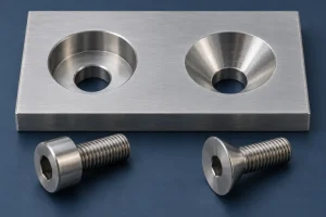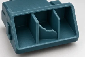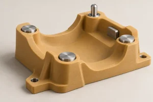

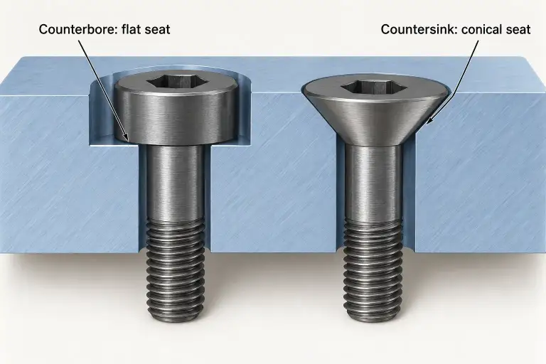
A counterbore provides a cylindrical recess with a flat bearing floor. A countersink provides a conical seat. For a recessed fastener, the choice starts with the surface under the screw head: a conventional socket-head cap screw bears on a flat seat, while a countersunk screw bears on a matching cone.
Both features can keep a fastener below the surrounding surface. That does not make them interchangeable. The head must contact the intended seat, leave enough material around the hole, and remain accessible to the assembly tool. A screw that appears flush can still have an incorrect contact condition.
The counterbore vs countersink decision therefore includes the actual fastener, its permitted installed position, and the plate section left after machining.
Choose the Head and Its Bearing Surface Together
Start with the fastener designation and dimensional drawing. The nominal thread diameter alone does not define the head diameter, height, angle, or transition into the shank.
A counterbore creates room around a head with a flat underside. Its diameter must accommodate the selected head and any washer that belongs in the joint. Its depth controls the position of that stack relative to the surrounding face. A cylindrical head can sit flush or below the surface when the recess has sufficient depth and the intended bearing surfaces meet.
The installation tool also needs access. An internal-hex screw needs clearance for its driver; a recessed external-hex head may need a substantially larger opening for the socket around it. The head fitting inside the recess does not establish that the assembly tool can reach it.
A countersink supports the conical underside of a countersunk head. The flat top associated with a flat-head screw should not be confused with a flat bearing underside. A countersunk screw placed directly on a counterbore floor does not receive the conical support its head was designed to use. A special washer or adapter would create a different joint that needs its own review.
If the fastener can remain above an already suitable machined face, neither recess may be necessary. If the task is to create a local flat bearing area on a rough or curved surface, the spotface versus counterbore guide addresses that separate decision.
Choose the bearing geometry first, then set the permitted head position. A requirement such as “no head projection above the finished face” is more useful than an undefined request to “make it flush.” Where excessive recess is also unacceptable, define both limits.
Match the Cone Angle Before Adjusting Its Depth
The included angle of a countersink is the full angle between opposite sides of its cone in an axial section. A 90° included angle places each side at 45° to the hole axis.
Confirm that angle against the selected fastener. For example, Bossard lists a 90° countersunk head for its ISO 10642 screw family. The same product information warns that the head geometry affects loadability and that the mounting situation needs checking. A fastener substitution therefore requires more than matching the thread designation.
When the screw-head angle and seat angle differ, contact can concentrate near an edge of the intended bearing region. Increasing countersink depth may bring the top of the head lower, but it does not correct that angular mismatch. The joint can look improved while retaining the wrong contact geometry.
Even with compatible nominal angles, the specified tolerances and the real head profile matter. Head rims, transitions, and permissible form variation should be considered when head position or contact is critical. Do not treat a simplified CAD cone as the complete purchased-fastener specification.
The conical interface also introduces a radial component of contact force. Its effect depends on the joint geometry, material, and clamp load. A thin ligament near an edge or a brittle component deserves separate review; countersinking is not automatically acceptable merely because the screw can be tightened.
Similarly, the presence of a counterbore does not establish a stronger joint. Head strength, bearing area, remaining section, thread engagement, and loading still govern the assembly. Compare the proposed fastener and seat together.
Check How Much Plate the Countersink Uses
A countersink becomes deeper as its included angle becomes smaller when the large and small diameters stay fixed. This relationship can expose a thickness problem before machining begins.
For an ideal conical seat, define:
- D: the large diameter where the cone meets the top reference plane.
- d: the smaller cylindrical hole diameter.
- θ: the included countersink angle.
- z: the axial distance from the top plane to the cone’s intersection with the smaller hole.
The geometric relationship is:
z = (D − d) ÷ [2 × tan(θ ÷ 2)]
Use degrees for θ when evaluating the tangent. The result has the same length unit as D and d.
Consider an illustrative 4.000 mm plate with D = 12.000 mm and d = 6.600 mm. These dimensions are chosen to demonstrate geometry; they are not a recommended countersink for a particular screw size. Assume parallel plate faces, a straight through hole, and a sharp theoretical cone-to-hole intersection. Ignore tolerances, edge breaks, and finishing changes for this comparison.
| Included angle | Cone depth z | Axial length below the cone within the 4.000 mm plate |
|---|---|---|
| 82° | 3.106 mm | 0.894 mm |
| 90° | 2.700 mm | 1.300 mm |
| 100° | 2.266 mm | 1.734 mm |
Values are rounded to three decimal places. The last column is plate thickness minus cone depth, measured along the axis. It does not represent a universal minimum wall requirement or prove resistance to pull-through.
At 90°, for example:
z = (12.000 − 6.600) ÷ [2 × tan(45°)] = 2.700 mm
The calculation does not authorize changing an 82° seat to 100° to save thickness while retaining the same screw. Each seat must remain compatible with its fastener. The table compares cone geometry, not interchangeable joint designs.
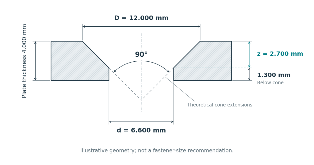
Check the cone depth and the remaining section together, using the angle required by the fastener. For a real part, include plate-thickness variation, countersink size and angle tolerances, nearby edges, and any backside pocket or cavity. A cone reaching the opposite face leaves a different hole geometry from the intended countersink above a cylindrical passage.
A counterbore needs a corresponding section check based on its specified floor depth. If either option removes too much material, consider a different head form, a thicker local section, or allowing the head to project. The appropriate change depends on the assembly load and available space.
Control the Recess in the Drawing and Machining Setup
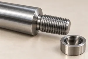
Define the smaller hole as well as the recess. State whether it is a clearance hole, a threaded hole, or another controlled feature, and whether it is through or blind. A recess callout alone leaves part of the joint undefined.
For a counterbore, identify its diameter, depth reference, and the required floor condition. Review the transitions at the smaller hole and at the outside corner of the floor against the head or washer that must seat there.
For a countersink, identify the large diameter at the reference face and the included angle. If depth is also specified, make clear how it relates to those dimensions. Diameter, angle, and depth are geometrically linked; independently assigned tolerances should not create conflicting acceptance limits.
An entry edge break is a separate requirement. As explained in the chamfer versus fillet guide, a small chamfer may serve only as a lead-in or burr removal feature. A general deburr note does not fully define a load-bearing countersink.
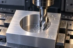
During machining, the tool must produce the specified seat relative to the associated hole. Counterbores may be made with suitable flat-bottom tooling or a milling path. Countersinks require the specified conical profile. In either case, tool access, rigidity, workpiece support, and chip removal affect the result.
Countersink size is particularly sensitive to axial tool position. A local height difference in the reference face can change the opening diameter when the program uses a common machine Z position across several holes. Cutter runout or chatter can also leave an irregular seat that is not adequately described by one diameter reading.
Identify the final surface-treatment condition. Coating on the seat or screw changes the assembled interface, while aggressive manual deburring can alter the top rim. The drawing should establish which condition is subject to dimensional and head-position acceptance.
Verify the Hole Geometry and the Installed Head
Inspection should separate the machined-feature requirements from the assembled result.
For an accessible counterbore, suitable measurements can establish recess diameter, floor depth, and the required relationship to the smaller hole or datum. A depth reading alone does not show whether a head is contacting an unwanted corner.
For a countersink, an opening-diameter check does not establish the cone angle. Select the measurement method for the stated characteristic. Starrett’s countersink gage guidance describes angle-specific gages that contact the conical surface and report the large diameter. That differs from a chamfer gage contacting the top edge. The gage must suit the feature, and its reading should not be treated as independent proof of every profile requirement.
Where angle, form, or location is critical, an appropriate optical, profile, or coordinate measurement may be needed. The inspection plan should address access and the available contact area rather than assume that any probe can measure a small cone reliably.
Then check the installed head against the defined reference surface using the specified fastener and assembly condition. Include the washer when one is required. Confirm that the head seats as intended, stays within its permitted projection or recess range, and remains accessible for installation and removal.
A functional assembly check provides useful evidence, but one conveniently available screw does not represent all permitted fastener variation. Likewise, installation torque alone cannot distinguish correct seating from geometric interference. Define the dimensional and functional checks needed for the joint.
For a CNC milling review, send the part drawing and model with the fastener designation, head profile, permitted head position, plate thickness, nearby cavities, and final finish. RapidEfficient can review the seat geometry, machining access, and inspection requirements before quotation.