
Type II anodize is commonly chosen for appearance and general corrosion protection. Type III, often called hardcoat anodizing, is a candidate when abrasion resistance matters. Choosing between them also changes the finishing decisions around a moving fit: coating thickness, sealing, and the dimensions accepted after treatment.
A drawing change from Type II to Type III should therefore trigger a review of the affected interfaces. A sliding guide can have an acceptable coating and still bind against its mating part. A guide may also slide freely during inspection but behave differently in service if its sealing state or operating conditions differ from those used for approval.
For a broader comparison with conversion coatings, plating, and other treatments, use the surface finishes guide. Here, the decision is between two anodizing types for an aluminum part whose fit and surface performance must both remain controlled.
Read Type, Class, and Thickness Separately
In the MIL-PRF-8625 system, Type II identifies conventional sulfuric-acid anodizing, while Type III identifies hard anodizing. Class 1 means non-dyed; Class 2 means dyed. These designations describe different requirements.
“Type III, Class 2” therefore calls for dyed hard anodizing. It does not mean a second hardness grade. Likewise, a non-dyed coating can have a natural color; Class 1 does not promise a colorless surface.
| Decision | Type II | Type III |
|---|---|---|
| Main reason to consider it | Appearance and general protective finishing | Abrasion-resistant functional surfaces |
| Color requirement | Specify the class and required appearance | Specify the class; do not identify hardcoat by darkness |
| Thickness requirement | Define the applicable specification and any additional thickness requirement | Define the applicable specification and the thickness needed for the function |
| Fit review | Check the finished dimensions at coated interfaces | Check the same interfaces before approving a change from Type II |
MIL-PRF-8625F with Amendment 2 provides the classification and acceptance requirements. Use the revision required by the drawing or contract, and review its defaults before adding project-specific requirements.
Do not identify the type from a thickness measurement alone. The ranges described in the Aluminum Anodizers Council reference guide overlap. The guide also explains that anodic coating develops both into the aluminum and outward from its surface. Total coating thickness and outward dimensional growth are different quantities.
An alloy designation, temper, and stock form belong in the review. A finish approved on one material should not become an unrestricted appearance or performance promise for every aluminum alloy.
Choose the Seal for the Wear Surface
Sealing is a functional choice, not just the last step on a process list. MIL-PRF-8625 treats sealing differently for Type II and wear-focused Type III applications. Type II is sealed unless otherwise specified. Type III intended for maximum abrasion or wear resistance is left unsealed; sealing can be specified when corrosion protection justifies reduced abrasion resistance.
This matters when a buyer requests hardcoat for an outdoor sliding guide. The wear track may need to survive repeated motion, while the exposed part also faces moisture. Those requirements need a deliberate finishing decision rather than an assumed “hardcoat and seal” default.
Define what the moving surface will contact: the mating material, load, travel, lubrication, and likely contamination. An abrasion result from a coating test does not establish the friction, clearance stability, or service life of that particular assembly.
For example, a guide that passes a clean, lightly loaded movement check has not demonstrated performance with abrasive debris present. A lubricant used during approval also needs to be part of the intended operating condition if the design depends on it.
Approve the wear surface in the same sealed or unsealed condition intended for production. If that condition changes, assess which coating evidence and assembly tests must be repeated.
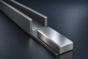
Check the Slot at Its Tightest Finished Condition
Consider an aluminum guide slot carrying an uncoated steel tongue. This is an illustrative design calculation, not a customer result or a standard anodizing allowance.
The machined slot is 20.100 ± 0.010 mm wide. The finished steel tongue is 20.000 ± 0.005 mm wide. For this example, assume the finishing review establishes a net inward movement of 0.020–0.030 mm at each slot wall.
That movement is measured from the original machined surface to the final surface after the agreed finishing route. It includes the net dimensional effect of preparation and treatment. It is not the total oxide thickness, and the assumed range must not be copied onto another part without process evidence.
Let:
- S be the slot width before finishing.
- T be the finished tongue width.
- g_L and g_R be the net movement of the two slot walls into the opening.
- C be the total width clearance after finishing.
Then:
C = S − g_L − g_R − T
The two wall movements are written separately because the fit depends on both surfaces. This is total clearance across the width, not clearance on each side of a centered tongue.
| Condition | Slot before finishing, S | Inward movement at each wall | Tongue, T | Finished total clearance, C |
|---|---|---|---|---|
| Nominal illustration | 20.100 mm | 0.025 mm | 20.000 mm | 0.050 mm |
| Minimum clearance | 20.090 mm | 0.030 mm | 20.005 mm | 0.025 mm |
| Maximum clearance | 20.110 mm | 0.020 mm | 19.995 mm | 0.075 mm |
At the minimum-clearance limit:
C_min = 20.090 − 0.030 − 0.030 − 20.005 = 0.025 mm
If the design requires at least 0.030 mm of total clearance, the nominal calculation passes but the minimum-clearance combination fails. All three input requirements can be individually satisfied while the assembly requirement is missed.
Budget the permitted finishing variation together with the machined dimensions and the mating part. A single nominal coating estimate cannot establish the minimum assembly clearance.
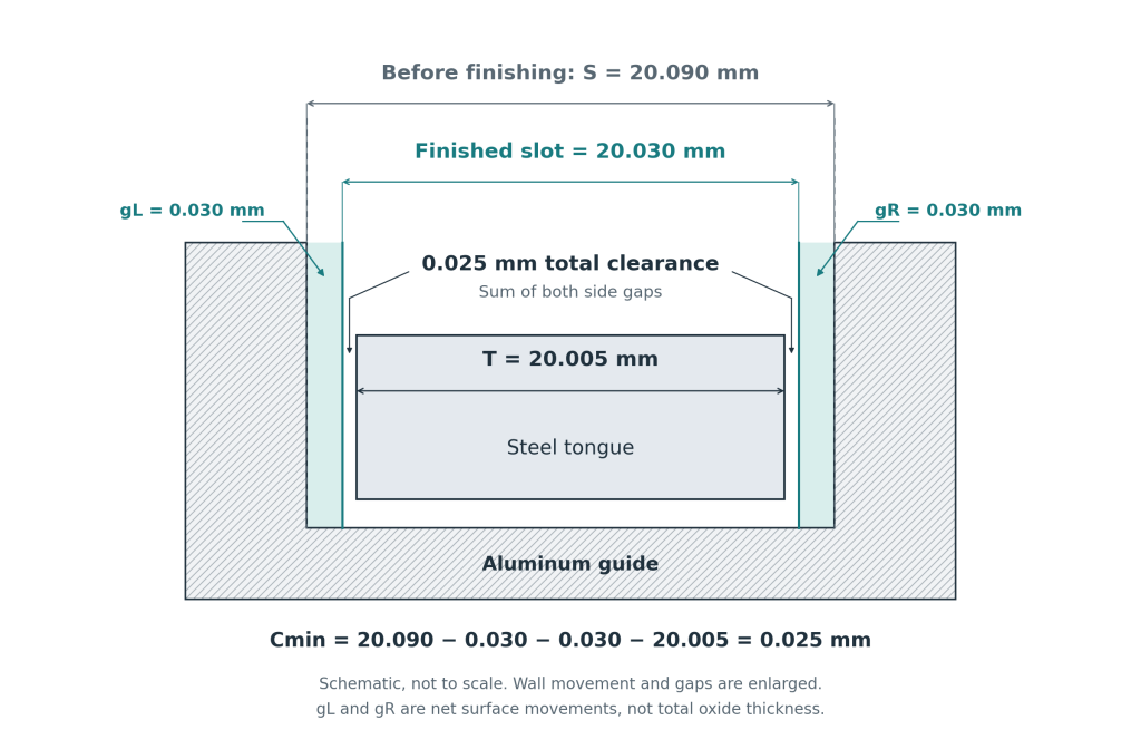
Possible responses include revising the pre-finish slot dimension, reducing an achievable process variation, changing the coating requirement, or redesigning the contact. Each response changes a different part of the engineering problem. Removing the coating from a wear surface simply to recover space also removes the intended surface treatment there.
This calculation covers width at a defined section. It does not establish straightness, parallelism, full-travel clearance, thermal behavior, or movement under load. A long guide may pass a local width check and still bind elsewhere. Establish the reference temperature and measure the functional sections or envelope required by the drawing.
The calculation is useful for either anodizing type. A Type II-to-Type III change requires new finishing inputs when the route changes; it does not justify reusing the old allowance merely because the base-metal CAD is unchanged.
Keep Masking and Rework Inside the Design
Masking can preserve a selected interface from anodic buildup, but it changes the surface condition at that location. On the guide, masking a mounting bore may be appropriate while the running slot remains coated. Masking the running slot would be a different functional decision.
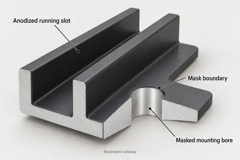
Show the masked zone and its boundary on the drawing. A finish transition should not drift into a sliding contact simply because the note says “mask critical areas.” Agree on the preparation sequence as well: excluding a surface from anodizing does not by itself define how that surface is protected during earlier cleaning or etching.
Keep rack-contact locations out of controlled running surfaces where their marks would interfere with the requirement. Resolve an acceptable contact area with the finisher rather than demanding an undefined mark-free part.
Post-finish cutting requires similar care. Machining a tight slot after anodizing can recover width by removing some or all of the coating from the cut surfaces. That may be an intentional route, but its remaining coating, exposed material, corrosion protection, and final dimensions need approval. It should not become an undocumented repair to an otherwise specified wear track.
If the concern is staining, burns, rack marks, or uneven appearance, the aluminum anodizing defects guide addresses those investigations. Changing from Type II to Type III should be justified by the required function rather than used as a general correction for an unidentified defect.
Approve the Coating and the Moving Assembly
The coating record and the assembly result answer different questions. Documentation can establish that the specified process was used; it does not replace measurement of the finished slot. A movement check can establish that the tested pair slides; it does not independently identify the anodizing type or prove the coating meets its requirements.
Before ordering the guide, align three sets of acceptance evidence:
- Coating condition: the governing specification and revision, type, class, thickness requirement where applicable, sealing, and any required coating-test evidence.
- Finished geometry: the slot and tongue limits, datums, measurement locations, masked boundaries, and the condition in which dimensions apply.
- Working interface: the mating part, load, travel, environment, and acceptance criteria for movement and wear when required.
Choose coating-measurement locations with the finisher. An accessible external surface or representative coupon may provide useful process evidence, but it does not directly measure dimensional growth on every wall inside a narrow feature. The finished slot still needs its own dimensional evidence.
If a supplier proposes Type III in place of Type II, request the revised thickness and sealing requirements, dimensional plan, and any affected validation. If the proposal goes the other way, determine whether the required wear performance remains supported. A substitution is an engineering change even when the quoted color remains the same.
For a CNC machining project review, provide the aluminum alloy and temper, the proposed anodizing specification, the mating-part drawing, and the surfaces that must retain a finished fit. Include the intended sealing condition and wear environment so machining allowance, masking, and inspection can be evaluated together.