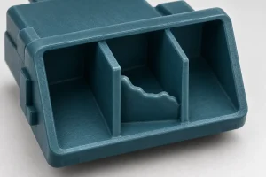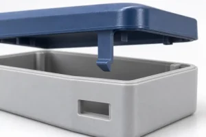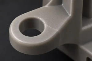

A connector housing can have a complete outer frame while one thin internal partition remains unfinished. Adding more material to the shot may increase the weight without completing that partition. The useful question is where the melt stopped and what prevented it from reaching the missing feature.
A short shot is an injection-molded part whose cavity was not completely filled, leaving part of the intended geometry absent. Insufficient material delivery is one possible cause. Restricted flow, early solidification, and trapped air can produce a similar result. Diagnosis needs both the incomplete part and the machine’s actual response during that shot.
Locate the Boundary of the Missing Plastic
Compare the suspect part with the drawing or an approved complete sample. Identify the missing edge, rib, partition, or other feature, then trace its connection back toward the gate. The last feature to fill is not necessarily the one farthest from the gate in a straight line. Branching paths and changes in section thickness affect the filling sequence.
First confirm that the feature failed to form. A feature that filled and then broke during ejection or handling needs a different investigation. Check for retained fragments, fracture surfaces, and repeated damage at the same location. A rounded incomplete edge can support a filling diagnosis, but its appearance alone does not establish the cause.
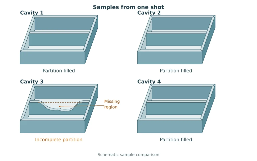
Keep samples identified by cavity and shot sequence. For a multicavity mold, compare parts from the same shot before comparing unrelated samples from a collection bin. This preserves the distinction between a persistent cavity-specific problem and a change affecting the whole mold.
| Distribution of missing plastic | Machine and shot evidence to compare | Question the comparison should answer |
|---|---|---|
| Similar incomplete regions across several cavities | Metering completion, actual transfer point, filling time, and pressure-limit events | Did a common delivery or control change affect the shot? |
| One cavity remains short while others fill | That cavity’s gate, runner or hot-runner branch, local temperature, and vent condition | What differs along the affected cavity’s supply and air-exit paths? |
| A thin partition stays incomplete while the surrounding body fills | Progress of the partition boundary during controlled filling trials | Does this branch stop advancing while another region continues to fill? |
| The missing region changes from shot to shot | Matched records of screw recovery, cushion, material supply, and thermal conditions | Does the change follow a repeatable machine or material event? |
These are investigation directions, not confirmed diagnoses. A shared machine condition can still affect the most difficult cavity first.
Track the missing feature by cavity and shot; total part weight cannot show where the material went.
Check What the Screw Actually Delivered
Compare the current cycle with the approved process record, including the actual machine response. A displayed setpoint does not prove that the machine reached or maintained it.
Metering and material supply. Confirm that screw recovery finishes and that material reaches the barrel consistently. Check the material grade, preparation, and any recent supply change. A larger metering setting does not by itself prove that more melt reached the affected cavity; transfer control and leakage also influence delivery.
Transfer from filling to packing. In a conventional velocity-controlled process, the transfer point changes control from the filling stage to the packing and holding stage. Establish which signal actually triggers that change. A position setting, timer, or pressure threshold should be interpreted according to the machine’s control logic. An unintended early transfer ends velocity-controlled filling while more of the cavity remains unfilled than intended. The packing stage must then complete that extra filling, which may be difficult if the pressure profile is insufficient or a thin flow path freezes.
Actual speed and pressure. When the pressure required to maintain the commanded injection speed reaches an active limit, the screw may slow down. Raising the speed command alone may then produce little improvement. Compare the velocity response with the pressure record before changing a limit. Machine injection pressure is not a direct measurement of pressure at the incomplete feature.
Cushion. When reported as a distance, cushion indicates how far the screw remains from its calibrated forward zero position at the controller’s specified measurement point. Confirm how the controller records this value and compare readings on the same basis. This position-based reading helps assess the melt reserve ahead of the screw. A remaining cushion does not prove that every cavity filled. A collapsing or inconsistent cushion calls for investigation of the settings and delivery system, including the non-return valve; it does not establish valve wear on its own.
A controlled fill-only trial can help separate first-stage filling from what packing subsequently adds. Use the machine’s appropriate procedure to remove the second-stage contribution, identify the samples, and compare their geometry with the production parts. Establish a suitable diagnostic fill level for that part instead of applying one universal percentage.
RJG’s discussion of establishing a fill-only part explains why visual fill, part weight, and the transfer point need different treatment for different geometries. A sample weighed after ejection is not a direct measurement of cavity fill at the instant of transfer.
A diagnostic fill-only sample is not a finished-part acceptance sample. Restore and assess the complete cycle before deciding whether the production defect has been corrected.
Trace the Flow Path That Stops First
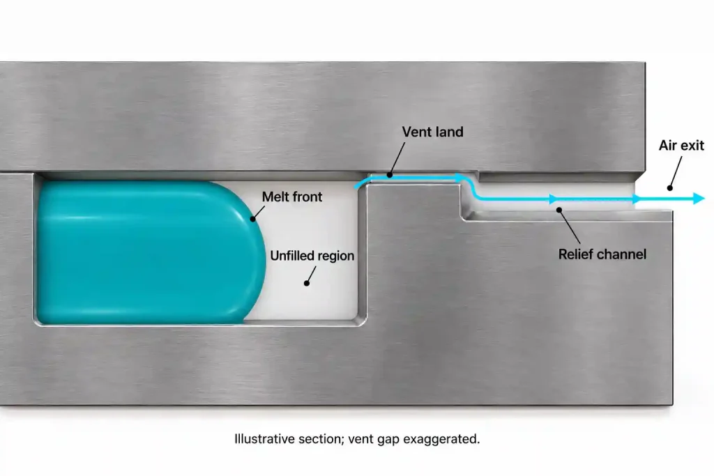
If delivery is repeatable but a feature remains incomplete, follow its melt path through the runner, gate, and connecting part sections. Examine both the entry restriction and the route by which displaced air must leave.
In Chapter 22, BASF’s engineering-thermoplastics troubleshooting guide identifies several distinct short-shot mechanisms, including insufficient metering, pressure loss through the gating system, inadequate venting, and a thin section near the gate freezing during filling. Its recommendations need to be applied within the selected material’s processing limits.
A restriction consumes pressure before the melt reaches the feature. Inspect for an obstructed gate, a cold restriction, or a runner branch that differs from the intended design. For a hot-runner mold, compare the affected zone’s response and gate operation with the other zones. Changing a gate requires review of the flow pattern, separation method, and finished mark, as explained in the injection molding gate guide.
A thin branch can stop filling while a thicker region continues. Consider a thin connector partition fed from a thicker surrounding wall. Melt may advance through the easier route while the partition cools. A controlled sequence of partial fills can reveal whether its boundary continues moving. The example is a diagnostic illustration, not a reported customer trial.
Faster filling can shorten the time available for the melt to cool before reaching a difficult feature, which may help thin sections fill before they freeze. However, it can worsen a problem where trapped air cannot escape quickly enough. Temperature changes also need to remain within the resin’s processing limits. Increasing holding time cannot reopen a flow path that has already frozen under the prevailing conditions.
Air needs a continuous exit route. Inspect the vent entrance and its path out of the mold. Cleaning an outlet does not resolve an incorrectly sized vent land, and deepening a vent without checking the resin and tool can introduce flash. Burn marks may support an air-trap investigation, but their absence does not rule one out.
If another cavity or an easier-flowing region starts to flash while the target feature stays short, preserve both observations. More plastic entering the mold has not demonstrated better filling at the required location. The injection molding flash guide covers the separate question of where the sealing interface is allowing melt to escape.
Change a justified variable, then compare the same feature and machine records under comparable thermal conditions. If the evidence points to an unsuitable section or feed path, review a design or tooling change rather than continuing to increase settings without a defined objective.
Prove the Feature Fills Across the Intended Run
Acceptance should identify the geometry that must be present. For the connector example, specify the partition’s required height, thickness, and continuity, together with any applicable assembly or electrical requirement. A complete outer frame or an acceptable overall weight does not verify those local characteristics.
Choose an inspection view that exposes the missing region. Small internal features may need magnification, controlled lighting, or another method that can reach the relevant surface. A camera looking only at the outer silhouette cannot approve a hidden partition. Automated inspection needs to be checked against representative acceptable and incomplete samples.
After a correction, verify complete production parts from each active cavity. Compare the previously short feature and any regions affected by the change, including flash, dimensions, surface condition, and relevant function. One complete shot demonstrates that filling was achieved once; repeatability needs evidence across the conditions included in the production approval.
Keep the sample identity, process revision, material condition, and inspection results together. Where restarts are part of the intended production plan, include them in the confirmation work. Set the sampling and acceptance requirements from the product risk and agreed control plan, without substituting an arbitrary universal number of shots.
For an injection molding project review, send the part drawing or CAD model, resin grade, and marked photographs of complete and incomplete samples. Cavity identity and available filling, transfer, and cushion records can help Rapid Efficient review whether the next step belongs in process investigation, tooling work, or a feature-design change.