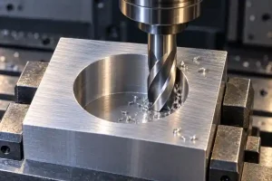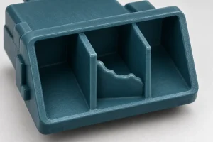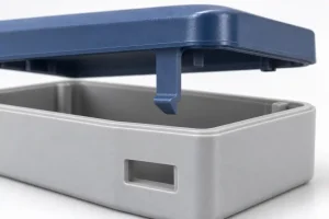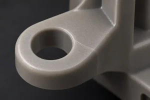

CNC machining removes material from stock; 3D printing builds a part layer by layer. For a functional component, the useful comparison is which route can deliver its material, working surfaces, and service performance at an acceptable cost.
CNC machining is a strong candidate when accessible features need controlled fits and an available stock material meets the application. Printing deserves consideration when the shape creates difficult cutting access, several components could be combined, or frequent revisions make a different construction useful. Neither process is limited to prototypes. A printed body with selected machined features or separate metal contacts can also be a production solution.
Start with what the part must do. Then compare the work needed to make, finish, inspect, and maintain it.
One Assembly Nest Can Need More Than One Process
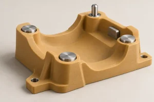
Consider a nest that supports a curved housing while an operator installs components. It has a shaped cradle, locating contacts, and mounting points connecting it to a workbench. This is an illustrative design, not a customer project.
The cradle may need to protect a finished housing from scratches. The locators must establish its position. The mounting points must remain secure during repeated use. Those requirements do not automatically call for one material or one manufacturing process throughout the nest.
A machined body can provide accessible locating features and mounting surfaces in a common setup. However, cutting a deep contoured cradle may require long tools, several orientations, or separate pieces. A printed body may simplify that shape, provided its material and construction can carry the assembly loads and withstand the working environment.
Compare three possible constructions:
| Nest requirement | Machined body | Printed body | Printed body with separate metal contacts |
|---|---|---|---|
| Support the curved housing | Check cutter access and whether selected pads can replace a full matching contour | Review the printed contact texture and clearance around non-contact areas | Keep the body clear where separate contacts establish position |
| Maintain locator position | Control the relevant features from the drawing datums | Verify the finished feature locations under the intended loading condition | Control the contact seats, hardware fits, and assembled positions |
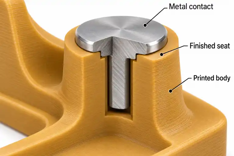
| Resist repeated contact wear | Select the body material or replaceable contacts for the duty | Confirm the printed material remains suitable after repeated loading and cleaning | Put wear-resistant material at the contacts; still assess the supporting body |
| Secure the nest to the bench | Review fastening details and the mounting face | Review local reinforcement and the chosen fastening method | Check how the fastener and contact loads enter the printed structure |
| Accommodate a housing revision | Assess which surfaces need rework or replacement | Assess whether a revised body can retain existing hardware | Make reusable hardware and replaceable geometry explicit |
A metal locator controls only the interface it provides; its position still depends on the body supporting it.
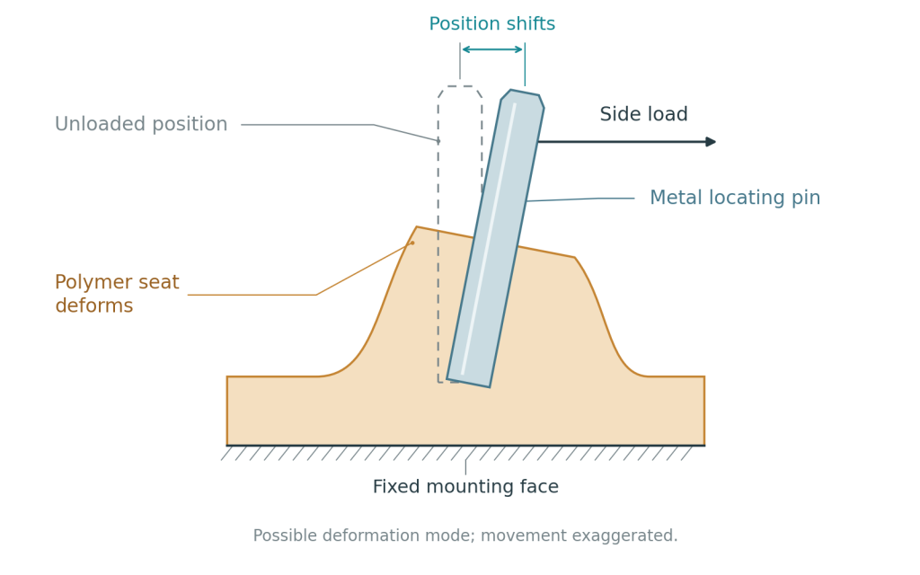
For example, an accurate pin installed in a distorted or moving seat does not create an accurate assembly. Check the installed contact locations and their stability, rather than approving the design from the pin supplier’s dimensions alone.
Separate hardware also introduces assembly work and possible movement at the joints. It earns its place when local wear, fastening, or replacement requirements justify those interfaces. Combining everything into a single printed piece can simplify assembly, but it may also make a worn contact harder to replace.
For fixtures used during cutting, the CNC machining fixture guide covers workholding, loading, and repeatability in more detail. An assembly nest should not be approved for cutting loads simply because it holds the same component.
“3D Printing” Is Not a Material Specification
A quotation for “3D printing” leaves a major decision unresolved. Filament extrusion, resin printing, polymer powder-bed processes, and metal powder-bed fusion do not produce interchangeable material conditions.
For the nest, identify the proposed material grade and printing process. Ask how the build orientation and internal construction relate to the loads. A change from a solid section to sparse infill changes the structure even when the outer CAD surface stays the same.
Stratasys’ FDM jig and fixture guide discusses orientation, fill choices, secondary machining, and added hardware. These are design options for FDM tooling, not universal instructions for every additive process.
The machined alternative needs an equally specific material description. A machined polymer, a printed thermoplastic, and a photopolymer described as having similar properties are not automatically substitutes. Likewise, the process name “CNC” does not remove directional properties already present in stock or guarantee a particular material quality.
Match the evidence to the application. For this nest, short-term strength may be less important than movement under sustained fastening load, contact wear, or resistance to the cleaning fluid. If temperature or moisture changes its dimensions, evaluate the condition in which the nest will actually locate the housing.
A short-term tensile-property value alone cannot predict creep under sustained load or establish resistance to contact wear and cleaning-fluid exposure. Test the completed nest with representative parts, loading, and exposure conditions. If the body material, build orientation, or contact construction changes, review which earlier results remain applicable.
Printing Moves the Access Problem
A cutting tool needs a physical route to the surface it machines. Tool diameter, reach, holder clearance, and workholding can constrain a CNC design. A nominally sharp internal corner or enclosed feature can require a design change, another process, or a multi-piece construction.
Printing can remove some of those cutting-access constraints. It introduces different access questions: how will supports, loose powder, or uncured resin be removed, and how will the working surfaces be finished?
The answer depends on the selected printing process. Do not assume that every printed cavity needs the same support system, or that an opening large enough to appear in CAD provides a practical cleaning route.
On the assembly nest, support contact on a locating surface could create extra finishing work. Moving that surface to a different build orientation may change other features. If a hole will be machined after printing, the cutting tool and fixture still need access to it.
A feature that can be printed is not necessarily a feature that can be cleaned, finished, and verified.
Metal printing makes the distinction especially clear. EOS’ metal additive manufacturing post-processing overview describes operations such as thermal treatment, separation from the build platform, support removal, and machining. The required sequence depends on the material, geometry, and application.
For a metal part with simple accessible bores and faces, adding a printing stage may create work without solving a useful geometry problem. For a shape that would otherwise require several machined components, printing may justify its downstream operations. The process name alone cannot settle that comparison.
Precision also belongs at the finished-feature level. Specify which dimensions, geometric relationships, and surface conditions matter. Layer height is not a complete dimensional-accuracy specification, and a general machining tolerance does not define every functional interface.
Where secondary machining is proposed, review the stock allowance, the locating method, and the part’s condition during inspection. The finished result must satisfy the drawing after the agreed manufacturing sequence.
Compare the Cost of Keeping the Part Useful
There is no universal quantity at which CNC becomes cheaper than 3D printing. A simple turned spacer, a deeply contoured nest, and a metal component requiring extensive post-processing have different cost structures.
For CNC, identify stock procurement, programming, workholding, cutting operations, finishing, and inspection. For printing, identify build preparation, material and machine occupancy, removal and cleaning operations, any required treatment, secondary machining, and inspection. Include hardware and assembly in either route when the design needs them.
Compare quantities for the same approved design and delivered condition. A quotation for an unfinished printed body does not cover the same work as an assembled, inspected nest. Conversely, a CNC quotation that includes unnecessary finishing on clearance surfaces may overstate what the application requires.
Delivery time needs the same treatment. A short print duration can be followed by a finishing queue. A short machining cycle can depend on unavailable stock or a fixture that has not been made. Ask for the sequence through acceptance, including the operations that control delivery.
For the nest, also compare what happens after wear or a product revision. Can the contact hardware be replaced? Must the whole body be remade? Does replacement require checking the assembled locator positions again? A lower purchase price can be useful, but it should be considered alongside those foreseeable costs.
Keep the evaluation focused. For a frequently revised assembly aid, the effort to update and requalify it may dominate. For a stable production tool used repeatedly, durability and replacement frequency may matter more. Neither outcome follows from choosing “additive” or “subtractive” alone.
When requesting a route comparison, identify the working surfaces, clearance regions, loads, contact wear, environmental exposure, and expected revision frequency. Include the first quantity and likely repeat demand. RapidEfficient can review requirements for CNC machining and 3D printing, including whether separate contacts or selected finishing operations belong in the proposed construction.