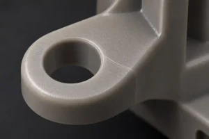

A plastic lid can click into place yet remain too loose in service, require excessive force to open, or lose retention after repeated use. Snap-fit design must account for the movement needed to assemble the joint, the geometry that keeps it engaged, and the movement allowed during release.
A snap fit joins components by temporarily deforming a feature so that it passes a mating obstruction and engages behind it. Cantilever snaps bend an arm; torsional snaps twist a supporting feature; annular snaps deform a circular connection. Their calculations differ. The example below follows a cantilever latch on a removable molded enclosure lid, where the assembly path and service access can be examined together.
Follow the Hook Through Assembly and Release
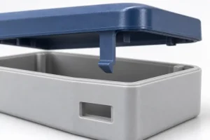
Consider a lid with an integral flexible arm and a hook that catches beneath a ledge in the housing. This is a design example, not a reported customer project.
During closure, the hook’s entry ramp contacts the ledge and bends the arm sideways. The arm reaches its greatest assembly deflection as the hook passes the obstruction. Once the hook clears it, the arm moves back toward its free position, leaving the retaining face behind the ledge.
These movements define different dimensions. The sideways deflection needed to pass the ledge is not the lid’s closing travel. The hook overlap after seating is another dimension. An internal component, stiffening rib, or enclosure wall must not block the arm before it completes the required movement.
For this removable lid, opening requires access to push the hook clear before lifting the cover. Define where a finger or tool can act and how far the arm can travel. A stop can limit excessive release movement, but its location must still allow disengagement across the dimensional tolerances.
Check the hook in its free, maximum-deflection, and fully engaged positions before fixing the surrounding geometry.
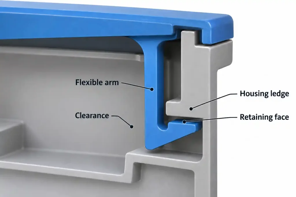
The insertion force also depends on the entry ramp and friction between the contacting surfaces. A shallow ramp may require more travel, while a different surface finish or mating material can change the force. The retaining face has a separate job: transferring the opening load into the housing. A latch intended to release by pressing a tab should not rely on users pulling hard enough to force that face over the ledge.
Check Arm Strain Before Increasing Thickness
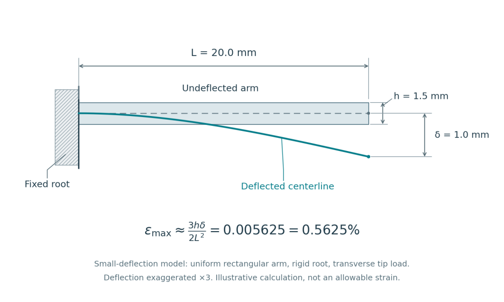
A simple beam model can show which geometry changes deserve closer review. For a slender cantilever with a constant rectangular section, a rigid root, and a transverse load at its free end, the small-deflection elastic approximation gives:
ε_max ≈ (3 × h × δ) ÷ (2 × L²)
Here, L is the flexible length from the fixed root to the end-load position, h is the thickness in the bending direction, and δ is the transverse end deflection. Use consistent length units; strain is dimensionless.
Covestro’s snap-fit design guide provides cantilever relationships for several cross sections and distinguishes deflection force from mating force. Select the relationship that matches the actual arm rather than applying the constant-section model to every latch.
For an illustrative arm with L = 20.0 mm, h = 1.5 mm, and δ = 1.0 mm:
ε_max = (3 × 1.5 × 1.0) ÷ (2 × 20.0²) = 0.005625 = 0.5625%
The following changes use the same idealized model. They are calculated comparisons, not material limits or test results.
| Geometry change | Flexible length L | Thickness h | Required deflection δ | Nominal maximum strain |
|---|---|---|---|---|
| Starting geometry | 20.0 mm | 1.5 mm | 1.0 mm | 0.563% |
| Shorter arm | 15.0 mm | 1.5 mm | 1.0 mm | 1.000% |
| Thicker arm | 20.0 mm | 2.0 mm | 1.0 mm | 0.750% |
| More clearance movement required | 20.0 mm | 1.5 mm | 1.2 mm | 0.675% |
Strain values are rounded to three decimal places in percent.
For a fixed required deflection, increasing the arm thickness raises the nominal bending strain in this model.
That result explains why adding material to a difficult latch can make assembly less forgiving. Reducing the obstruction or increasing the flexible length may help, but each change also affects engagement, available space, and the load carried after closure. Increasing width does not reduce the strain predicted by this equation; it increases the force needed to produce the same deflection under the stated assumptions.
The calculation does not include the local stress concentration at the root fillet. It also does not describe a flexible supporting wall, a short thick arm, a tapered section, or large rotation. During actual assembly, the contact point can move along the ramp. Those conditions may require a different analytical model or contact analysis.
No pass/fail conclusion follows from 0.563% alone. Compare the predicted strain with suitable design data for the specified resin grade, temperature, conditioning, loading rate, and number of operations. Tensile elongation at break is not a general allowable strain for a reusable latch. Reinforced grades may also need direction-dependent properties.
Keep Engagement When the Arm Recovers
The enclosure needs sufficient hook overlap after the arm returns, including variation in both molded components. Examine the assembled dimensions from the surfaces that locate the lid and housing. A hook dimension measured from an unrelated outside face can hide movement elsewhere in the assembly.
Check two tolerance conditions separately: the combination that demands the greatest assembly deflection, and the combination that leaves the least engagement after seating. They need not involve the same dimensional extremes. Warpage or an incorrectly seated cover can also change the contact position.
Aim to let the arm recover substantially after the hook passes the ledge. If a deliberate preload is needed to control rattle or compress a seal, treat it as a continuing load case. Geometric engagement, contact pressure, and sealing pressure are different requirements.
A plastic arm held at a fixed bend can gradually exert less force through stress relaxation. Under a sustained load, its deflection can increase through creep. Delrin’s explanation of creep and stress relaxation distinguishes these conditions; the response depends on material and environment. Its grade-specific data should not be transferred to another resin.
For the lid, this means that strong initial spring pressure is insufficient evidence of lasting retention. Check whether the hook remains engaged as the arm and mating wall move under the service load. Also check the hook section, ledge contact area, and housing support: the beam calculation above does not evaluate their strength.
On the drawing, identify the mating ledge, hook overlap, root transition, and free-state arm position. Define assembly and release force requirements with their direction, contact point, and test condition. A general note such as “snap fit must be tight” leaves these decisions unresolved.
Resolve the Hook’s Mold-Release Path
The hook may pass over the housing ledge during assembly while still trapping the steel that forms its retaining face. Review mold release separately from product operation.
A window beneath a hook can sometimes allow forming steel to pass through the part and create the retaining face with a suitable shutoff. Other geometries may need a lifter, slide, or design change. The undercut release guide explains these tooling choices. Adding a window also changes the enclosure: check access protection, sealing needs, wall stiffness, and clearance to internal components.
Stripping a flexible hook from the mold is another possibility for selected designs. Its suitability depends on the release geometry, resin behavior at ejection, support, and permitted deformation. A latch that survives room-temperature assembly has not thereby proved that it can be stripped safely from the tool.
Review the root radius, local wall thickness, and draft together. A smoother root transition can reduce a sharp-corner stress concentration, but adding a large mass of plastic at the junction can complicate cooling and dimensional control. Draft also changes the arm section along its height or length; the final molded geometry should be used in the mechanical assessment.
Gate placement and filling deserve attention where the arm joins the enclosure. If flow fronts meet in that loaded region, evaluate the resulting joint conditions. The knit-line strength guide addresses why surface appearance alone cannot establish the strength of that region.
Test Retention After the Intended Use
A useful latch test reproduces the way the cover is located, closed, held, and opened. A fixture that braces the housing directly behind the ledge may make the joint appear stronger than it is in the product. Use the intended supports and apply the opening load at the relevant location.
Separate closure effort, resistance to unintended opening, and force needed for deliberate release. Record force and movement where they affect acceptance. Inspect for cracking, permanent deformation, wear, or incomplete engagement after the specified operations. An audible click confirms neither the amount of hook overlap nor the remaining retention force.
Measure the retained function after the required cycling and dwell conditions, as well as on the first assembly.
Set cycle counts, dwell time, temperature, conditioning, and acceptable forces from the product requirements and material evidence. A lid opened occasionally for service needs a different validation plan from a closure operated every shift. If the joint must maintain gasket compression, include the required sealing evaluation after conditioning and cycling.
Printed samples can help examine access, collisions, and the sequence of movement. Their material, surface, and build direction can change the force and failure behavior. The injection molding versus 3D printing comparison explains that validation boundary. Use representative molded parts for production approval, with the intended resin and relevant dimensional variation.
For a snap-fit molding review, provide both mating models, the assembly and release directions, resin requirements, expected opening frequency, and service loads. Mark the surfaces that control engagement and identify any sealing requirement. RapidEfficient’s injection molding services can review the geometry and tooling route before quotation; agree on the required functional testing and responsibility for it before production approval.