An injection molding gate is the opening through which molten resin enters the mold cavity. Its location must support filling and packing while leaving an acceptable surface after the gate connection separates or closes.
A gate hidden on a gasket land may protect appearance and still interfere with sealing. A gate on a broad visible face may help the part fill but leave an unwanted mark. Choose the gate type, flow path, and permitted gate mark together, before approving the tooling layout.
Choose the Gate With Its Separation Method
The runner carries resin toward the cavity; the gate is the final connection into it. Gate types differ in how they feed the part and how the molded connection separates.
| Gate type | How it feeds or separates | Design question to resolve |
|---|---|---|
| Edge or fan gate | Feeds at the parting line. A fan gate spreads the entry across a wider edge. The connection normally needs cutting or trimming. | Is there room to reach the connection and remove it without damaging the finished edge? |
| Tunnel or submarine gate | Enters below the parting line and can shear during mold opening or ejection. | Can the runner release and the connection break reliably with the selected material? |
| Curved tunnel or cashew gate | Reaches a less exposed surface through a curved passage. The runner must withdraw from that passage. | Can the runner flex and release without breaking inside the tool? |
| Cold-runner pinpoint gate | Provides a small entry, often through a three-plate mold arrangement that separates the runner. | Can the small opening provide enough flow and packing while breaking cleanly? |
| Thermal hot-tip gate | Feeds from a heated drop; local thermal control allows the gate to seal between cycles. | What point, depression, or surrounding surface mark is acceptable? |
| Valve gate | A moving pin mechanically closes the gate opening. | Does the resulting witness mark meet the requirement, and does the project justify the added mechanism and maintenance? |
Automatic separation does not establish that the remaining surface is acceptable. A tunnel gate can leave a mark, and a valve gate can leave a visible ring even when its projection is small.
Covestro’s Part and Mold Design guide illustrates these distinctions, including curved-tunnel release requirements and the witness mark from a flush-closing valve gate. Check material-specific recommendations before applying a gate design to a different resin.
“Hot runner” also does not mean “valve gate.” A hot runner describes the heated distribution system; its outlets may use different gate mechanisms. Ask for a section through the proposed gate when a name alone leaves the construction unclear.
Follow the Melt Around a Display Opening
Consider an illustrative instrument bezel with a large display opening, a visible front face, a rear gasket land, and mounting ears. This is a design example, not a reported customer project.
First mark the surfaces that cannot carry a gate connection or trimming damage. The front face may have a cosmetic restriction. The gasket land needs uninterrupted contact. A mounting ear may carry an assembly load that makes a removal notch unacceptable.
A hidden outside edge can be a candidate, but it still needs a filling review. Melt entering from that edge divides around the core that forms the display opening. The separated fronts then meet elsewhere in the bezel, creating a potential weld-line region.
A single gate can still produce a weld line when the flow divides around an opening.
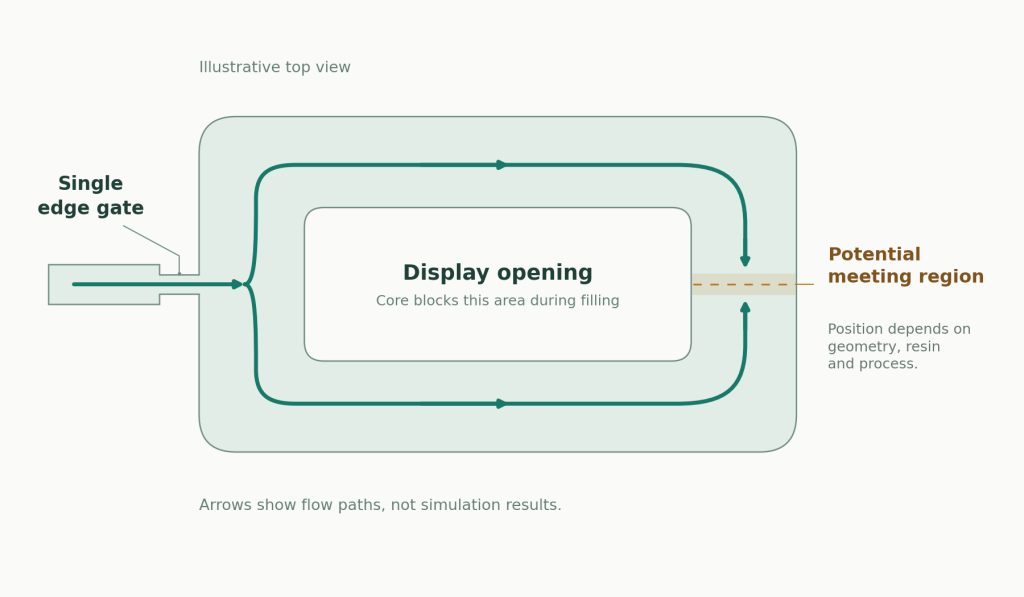
Suppose the predicted meeting region falls near a loaded mounting ear. Moving the gate may move that region, but the new location must also satisfy the cosmetic and sealing restrictions. The decision concerns the whole flow path, not just the small area where the runner attaches.
Adding another gate may shorten the distance resin travels. It also changes where fronts meet and how the cavity fills. It is therefore another layout to evaluate, rather than an automatic cure for a difficult single-gate design.
Use the proposed resin grade, wall sections, and gate arrangement when comparing filling alternatives. A sketch can identify a likely split-and-rejoin path, but it cannot establish the exact meeting position or resulting joint strength. Flow analysis can help assess the layout; molded samples and relevant functional tests provide the production evidence.
For a reinforced resin, include the effect of the changed flow direction on fiber orientation. Moving a gate after sampling can affect dimensions and loaded features as well as the visible mark.
Size the Gate for Flow and Packing
A smaller gate may leave less material to remove, but appearance is only one constraint on its size.
For a rectangular gate, identify its width, thickness, and land length. The land is the short passage between the runner and the part. Increasing its length adds flow resistance under otherwise comparable conditions. Two gates with the same entry area can therefore behave differently if their land lengths differ.
The opening must pass the required flow without unacceptable pressure loss or shear. It must also support the required packing before the feed path closes. Reducing gate size solely to hide the mark can make one or both tasks harder.
A larger opening can ease the restriction but change gate sealing, separation force, and the remaining mark. Review those effects together instead of choosing one gate-to-wall ratio for every resin and geometry.
Enlarging the gate also cannot correct every packing problem. A thin section between the gate and a heavy feature may stop feeding that feature as it solidifies. The sink marks in injection molding guide explains the difference between gate sealing and loss of a local packing path.
Before approving a particularly small gate, ask what supports its suitability for the actual material and part: resin guidance, filling analysis, comparable tooling experience, and planned trial checks. A clean-looking gate sketch is not that evidence.
Define the Vestige Relative to a Real Surface
Gate vestige is the residual feature at the feed connection after separation. “Trim flush” is incomplete unless the reference surface and permitted result are clear.
For a gate in a recess, flush with the recess floor differs from flush with the surrounding face. Protolabs’ gate-design discussion illustrates how a recessed gate area can keep a trimmed mark within the surrounding surface envelope. The recess and the remaining mark still need compatible limits.
Consider a simplified example with dimensions chosen only to demonstrate the relationship:
- Recess depth below the surrounding local face: 0.40 ± 0.05 mm.
- Maximum remaining gate height above the recess floor: 0.30 mm.
- Both dimensions are measured normal to the same local face.
At the shallowest permitted recess:
Minimum recess depth = 0.40 − 0.05 = 0.35 mm
Minimum setback below the surrounding face = 0.35 − 0.30 = 0.05 mm
Under those assumptions, the remaining gate stays at least 0.05 mm below the local surrounding face. These values are not standard gate tolerances or a supplier capability claim.
The calculation covers only local geometry. Warpage, a mating component entering the recess, or a later coating can change the assembly clearance. Account for those effects separately where they apply. The recess also changes the local wall section and needs a molding review.
Control the remaining gate against the surface that matters to the assembly.
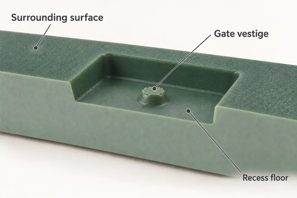
Height alone is not enough. Define the allowed footprint and any limit on material removed below the intended surface. A low vestige with a wide gouge may still damage a sealing edge or reduce the section at a loaded feature.
Appearance needs a separate judgment. Gate blush is a local visual change around the gate; it is not simply a projection that trimming removes. Specify the permitted viewing area and appearance boundary, using the injection molding surface finish guide where finish zones and observation conditions need clarification.
Approve the Gate Location and Finished-Part Requirements
The tooling approval should show the proposed gate location, permitted gate area, separation method, and finished-surface limits on the same part revision. Identify who approves a relocation if the first trial reveals a filling or appearance problem.
Review the gate with the surrounding tooling. A proposed location may conflict with a slide, cooling passage, ejector, or the access needed for trimming. Resolving those conflicts after machining the tool can require more than moving a point on the CAD model.
During sampling, retain parts that show the condition before and after gate removal. Check the final delivered condition, including any specified coating or assembly operation. For a multicavity tool, record the cavity number for each sample and compare the gate area and separation quality across cavities.
If a gate moves or changes size, identify which prior approvals need to be repeated. The affected items may include the gate mark, weld-line location, local strength, packing response, or final part dimensions. A cosmetic improvement alone does not establish that those other requirements remain satisfied.
For a gate review, send the part model with cosmetic restrictions, sealing lands, loaded features, and permitted gate areas marked. Include the resin grade and any proposed vestige limit. Rapid Efficient can review these requirements with the mold layout and sampling plan through its injection mold tooling service.