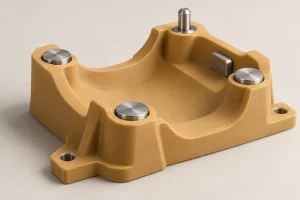
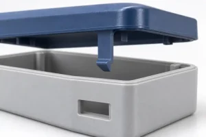
A molded enclosure may need a textured grip, a smooth label recess, and an untextured mating rim. A general note such as “SPI-B1 on visible surfaces” leaves important decisions unresolved: where each finish stops, whether the textured wall can release cleanly, and which appearance the inspector should accept.
An injection molding surface finish specification should identify the mold finish, the surfaces receiving it, and the acceptance requirements for the molded part.
The resin grade, color, fillers, geometry, and molding conditions all influence the result. Choosing a finish code is one part of that specification.
Use SPI Grades to Describe the Mold Surface
For an as-molded surface, polishing or texturing is applied to the tool. The plastic reproduces that surface during molding, with the result affected by the material and process.
The following SPI surface finish chart summarizes the main preparation families. It provides a starting point for discussing the mold surface; it does not guarantee the appearance of every plastic molded against it.
| SPI Grades | Mold Surface Preparation | What the Family Identifies |
|---|---|---|
| A1–A3 | Diamond polishing | High-polish mold finishes |
| B1–B3 | Abrasive-paper finishing | Paper-finished mold surfaces |
| C1–C3 | Stone finishing | Stone-finished mold surfaces |
| D1–D3 | Dry blasting | Blasted mold textures |
The DME mold and tool finish guide lists preparation methods and approximate resulting roughness for these mold finishes.
Even preparation descriptions that sound similar can refer to different surfaces. SPI-B1 uses 600-grit paper, while SPI-C1 uses a 600 stone. The shared number does not make the finishes interchangeable.
Keep SPI, VDI, and Named Textures Distinct
Drawings may specify SPI grades, VDI designations, or named texture patterns. Do not substitute one for another solely because a comparison chart lists similar roughness.
A named grain also describes a pattern. Its shape, spacing, direction, and depth can affect appearance and release. A single Ra value cannot describe all those characteristics.
Keep the agreed designation and reference sample together. If the toolmaker proposes an alternative, compare and approve the resulting surface before treating the two specifications as equivalent.
Map the Finish Around One Enclosure
Consider an illustrative handheld enclosure with an outer grip, a label recess, a mating rim, and internal ribs. These areas serve different purposes and should not automatically receive one finish.
A surface map connects each drawing zone to its tooling instruction and acceptance requirement.
| Enclosure Zone | Intended Result | Information to Specify |
|---|---|---|
| Outer grip and visible sidewall | Consistent texture and appearance | Texture designation, sample reference, boundary, and appearance limits |
| Label recess | Surface suitable for the selected label or printing process | Local finish, texture exclusion boundary, and adhesion or print-validation requirements |
| Mating rim and locating features | Reliable assembly fit | Functional dimensions, local surface requirements, and areas excluded from decorative texture |
| Internal ribs and bosses | Functional molding and assembly | Required local finish, permitted marks, and restrictions affecting fit or release |
A smooth label recess should not inherit the surrounding texture by accident. Its finish must also suit the selected adhesive or printing process; making it smoother alone does not prove adhesion.
Likewise, a narrow locating edge should not receive decorative texture without checking its effect on contact and fit.
Mark the finish boundary on the model or drawing, including where it crosses a radius or meets a functional surface.
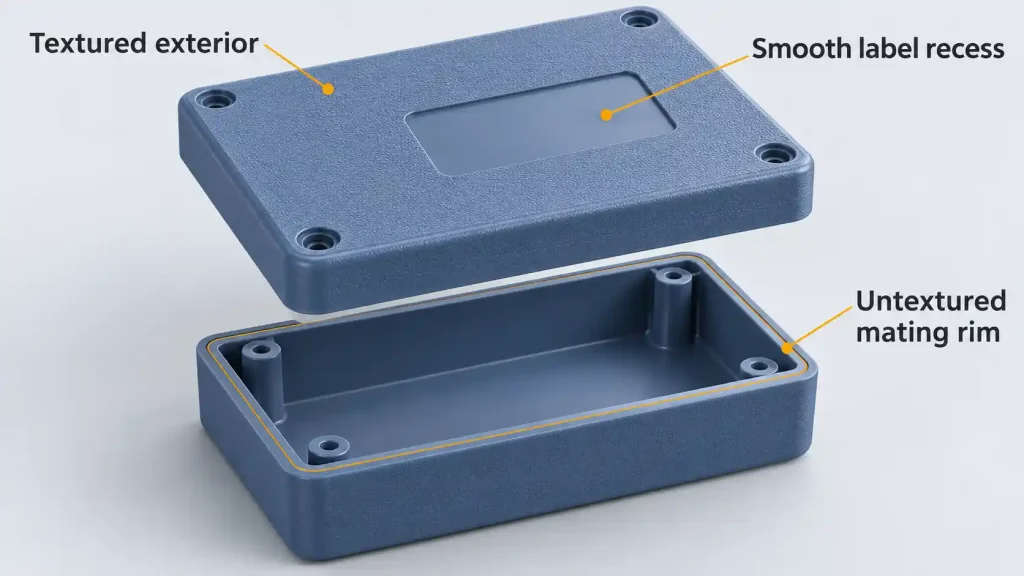
A color-coded view is useful, but the zones also need identifiers that remain clear in a monochrome drawing. “All visible surfaces” may be ambiguous when the part looks different before and after assembly.
Check whether the toolmaker can produce the proposed transition consistently. A boundary running through a small radius needs more precise definition than a broad textured face ending at a clear geometric edge. Agree on the transition location and its acceptable appearance before finishing the tool.
The map also helps control cost. A hidden rib rarely needs the same cosmetic treatment as the outer grip unless another requirement justifies it. An undefined transition, however, can require tool rework after the first molded samples reveal the disagreement.
Evaluate the Finish in the Resin You Will Mold
A texture plaque is useful only when its material and purpose are understood. It can communicate the desired grain, but a plaque made in one resin does not establish the appearance of another.
For example, an unfilled ABS plaque may help select a texture for a glass-filled nylon enclosure. It does not prove that the enclosure will have the same gloss, grain definition, or visual uniformity.
Identify the resin grade, reinforcement, and color used for each sample. If the exact production combination is unavailable, record the substitute and treat approval as preliminary.
For reinforced materials, evaluate the actual grade and molding route before committing to a demanding cosmetic requirement. Additional mold polishing may not resolve an appearance difference caused by the material or its processing conditions. Equally, the presence of reinforcement alone is not enough to rule out a particular appearance.
A practical approval sequence separates two questions:
- Does the reference communicate the appearance the buyer wants?
- Can the proposed material, tooling, and molding process reproduce an acceptable result on this part?
Early samples help answer those questions. Consistency should then be checked across parts produced with the intended tooling, resin, color, and agreed molding conditions.
Check Texture Against the Direction of Release
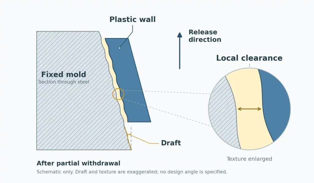
A textured wall may remain in contact with the mold as the part moves during ejection. Insufficient clearance can leave scuffing or drag marks even when the intended grain has formed.
Draft is the taper that helps those surfaces separate. Its adequacy depends on the local release direction and selected texture, rather than one angle applied everywhere.
Texture depth and shape affect contact during withdrawal. Part geometry and shrinkage also matter: a wall shrinking onto a core can present different release conditions from a surface moving away from the surrounding cavity.
Review the entire textured area, including corners, curved transitions, and short sections where local draft changes. A wall that released successfully with a polished finish may need another review after a deeper texture is selected.
If release is doubtful, possible changes include increasing local draft, selecting a shallower texture, moving the texture boundary, or changing the tooling arrangement. Check each option against the part’s appearance and function.
Approve the texture and the release geometry together.
Where a snap feature or recess blocks withdrawal, the undercut release guide explains why adding draft alone does not remove a trapped feature.
Include these decisions in the injection mold tooling review before committing to the final surface treatment. A late texture change can affect geometry, release, and tooling work as well as appearance.
Investigate the Mark Before Changing the Finish
A visible defect does not automatically mean the selected SPI grade or texture is wrong. Use the location and shape of the mark to decide what to investigate.
- A depression above a rib or boss: Review local material thickness, shrinkage, packing, and cooling. Changing the texture does not restore the missing surface geometry.
- A line where flow divides and rejoins: Investigate the weld line and local texture replication. Gate placement and filling conditions may matter more than additional polishing.
- A streak aligned with ejection: Check contact during release, local draft, and the ejection arrangement.
- A local change in sheen: Compare material and molding conditions as well as the tool surface before deciding to polish the affected area.
Texture may make a blemish less noticeable under some lighting, but shadows can also emphasize a local depression. Evaluate the part under the agreed inspection conditions rather than assuming a rougher finish will hide the defect.
Before authorizing tool rework, identify whether the problem originates in the tool surface, part geometry, filling, cooling, or release. The corrective action should address that cause.
Approve Appearance on a Defined Part and Viewing Setup
A reference plaque helps select a finish. Production approval also needs molded parts that represent the intended resin, color, tooling, and agreed process.
Retain identified samples so that “match the approved appearance” refers to a specific physical reference. Record the part revision, material and color identification, sample approval, and cavity identity where relevant.
For the enclosure, the surface map should define where appearance is judged. A small mark inside a hidden screw pocket may have a different acceptance limit from the same mark on the outer grip.
Agree on lighting, viewing distance, viewing angle, and part condition. Where judgment is subjective, acceptable and unacceptable boundary samples can clarify the limits better than an instruction such as “good commercial finish.”
If painting, coating, or plating follows molding, identify the stage covered by each approval. An approved as-molded sample does not establish the final coated appearance. Define the required surface preparation and approve the finished delivery condition separately.
Give Numerical Gloss Requirements a Measurement Method
If gloss is controlled numerically, specify the measurement method, geometry, and location alongside the acceptance limit. A gloss number without those details leaves room for inconsistent inspection.
When comparing production parts with an approved reference, keep the measurement method, location, and sample orientation consistent. Do not compare readings taken under different geometries as though they represent the same measurement.
The instrument must also suit the available surface. A narrow curved rim or deeply textured region may not support the same setup as a broad flat plaque. Agree on a suitable measurement area before making that reading an acceptance requirement.
Keep appearance approval and dimensional approval identifiable in the submission. A passing dimensional report does not document texture uniformity, color agreement, or acceptable ejection marks. The first article inspection guide explains how to connect requirements with their supporting evidence.
For a molded enclosure, share the surface map, exact resin and color requirements, finish references, critical mating areas, any planned coating, and expected quantity through our injection molding services. Rapid Efficient can review the finish boundaries, release considerations, and sample-approval requirements with the proposed tooling route before quotation.