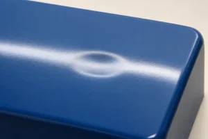
Sink marks in injection molding are local depressions that develop when a cooling section shrinks without enough material compensation. They often appear opposite ribs, bosses, or other areas with extra material behind the visible wall.
The useful question is whether that section can still receive packing material while it contracts. More holding time can help when pressure is removed too early. It cannot add material through a frozen flow path.
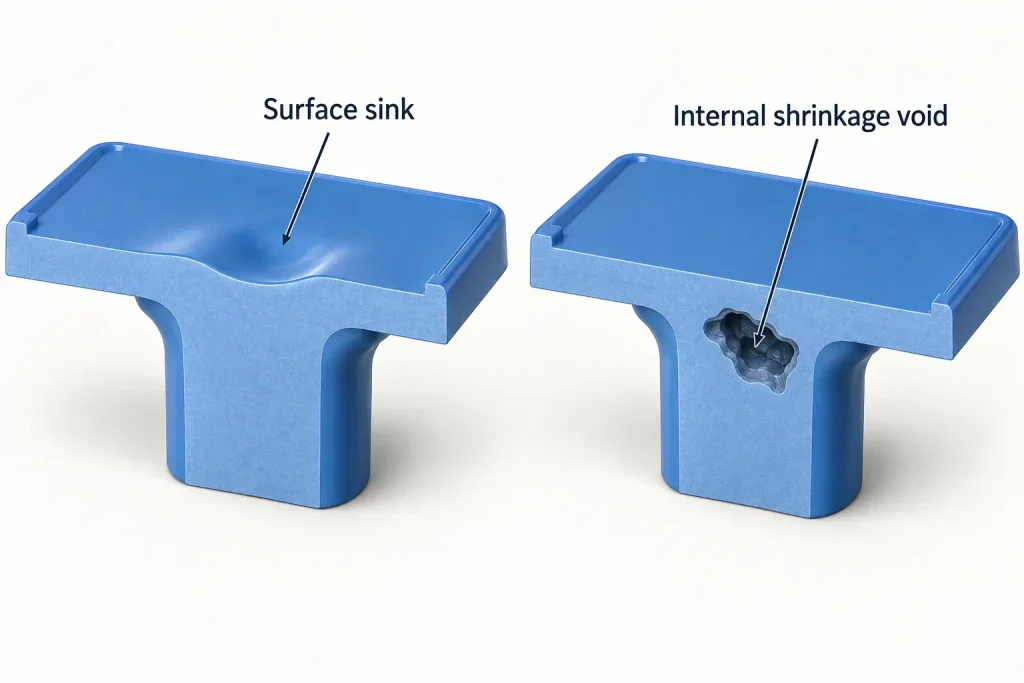
A smoother surface also needs careful interpretation. Shrinkage can leave an internal void when the outer skin resists movement, so appearance alone does not establish the condition inside a critical section.
Look Behind the Depression
Consider a molded equipment cover with a shallow depression on its outside face, directly opposite a mounting boss. This is an illustrative design situation, not a reported customer project.
In a section through that location, inspect the boss base, adjoining rib, and connecting radii together. A drawing may specify a consistent main wall while the intersection still contains a much thicker local mass. Examining only the wall away from the boss misses the feature most likely to explain the mark.
The outer layers cool before the interior. As the hotter material contracts, the surface can be pulled inward. If the skin is sufficiently rigid, an internal shrinkage void may develop instead. Both defects can also occur in the same region.
BASF’s engineering thermoplastics troubleshooting guide discusses sink marks and voids separately and relates both to local material accumulation and inadequate compensation during cooling.
A visible sink does not prove that a void exists, and a smooth surface does not rule one out.
Record whether the depression is already visible at ejection or becomes clearer after cooling. Keep sample age and inspection conditions consistent when comparing trials. A part examined immediately after release and one examined later may give different impressions of the same molding condition.
A depressed ejector mark or a distorted wall can have a different cause. Check the location against the tooling and the section geometry before treating every indentation as shrinkage.
Packing Must Reach the Section Before the Path Closes
In conventional thermoplastic injection molding, packing and holding compensate for part of the volume loss as the resin cools. Their effect depends on the pressure reaching the relevant region and the remaining ability of material to flow.
The entire route matters: nozzle, runner, gate, and the section between the gate and the thick feature. A thin connecting wall can restrict or freeze before a remote boss has received adequate compensation. Raising the machine’s pressure setting does not establish that the same pressure reaches that boss.
In a conventional combined packing/holding stage, both pressure and duration can affect material compensation while the flow path remains open. Extending that stage may allow more resin to enter and can prevent premature backflow through an unsealed gate.
Once a feeding path has frozen, additional holding time cannot send more resin through it. Neither more pressure nor more time removes a heavy intersection or repairs an ineffective cooling circuit.
If additional pressure creates flash near the gate while the distant depression remains, record both results. Investigate pressure transmission and local geometry rather than approving the change based on one feature. The injection molding flash guide addresses the separate sealing problem exposed by that trial.
Temperature changes also affect several conditions at once: melt flow, freezing, cooling, and surface stiffness. Follow the selected resin’s processing guidance. A lower temperature is not a universal remedy, especially when it makes the flow path close sooner.
Use Part Weight to Test the Holding Window
A gate-seal study can help determine whether extending holding time still changes the amount of material retained in the part.
For a conventional gate that freezes closed, a process engineer can hold the pressure profile and other relevant conditions steady while increasing holding time in controlled steps. After stabilization, collect repeated samples at each setting and compare their weights.
Keep cavity identity, runner removal, and sample conditioning consistent. Use a balance capable of resolving the expected differences. Keep the total in-mold cooling interval consistent across the trial, adjusting the remaining cooling interval according to the machine’s timer logic when holding time changes. Allow enough cooling for stable ejection. Otherwise, a changed thermal cycle can obscure the effect of holding time.
RJG’s gate-seal study guidance describes weighing parts at different holding times and using cavity-pressure evidence when weight measurements are impractical.
The following table is a way to interpret trial evidence. It contains no supplier test data or recommended machine settings.
| Trial observation | What it can support | What still needs checking |
|---|---|---|
| Longer holding time increases repeatable part weight and reduces the sink | The earlier holding stage may have ended before sufficient material was retained | Dimensions, flash, release, and whether the improvement persists across cavities |
| Weight reaches a repeatable plateau, but the local sink remains | Extra holding time at that pressure profile is no longer increasing retained mass measurably | Local section thickness, cooling, gate restrictions, and whether the region was adequately packed before flow stopped |
| Overall weight rises, but a remote boss still sinks | More material is being retained somewhere in the part | Distribution of packing; total weight cannot identify where that material went |
| Weight varies widely at one setting | A stable trend has not yet been established | Shot delivery, transfer, cushion, material condition, and measurement consistency |
A weight plateau helps define the holding window; it does not certify every local section as free of shrinkage defects.
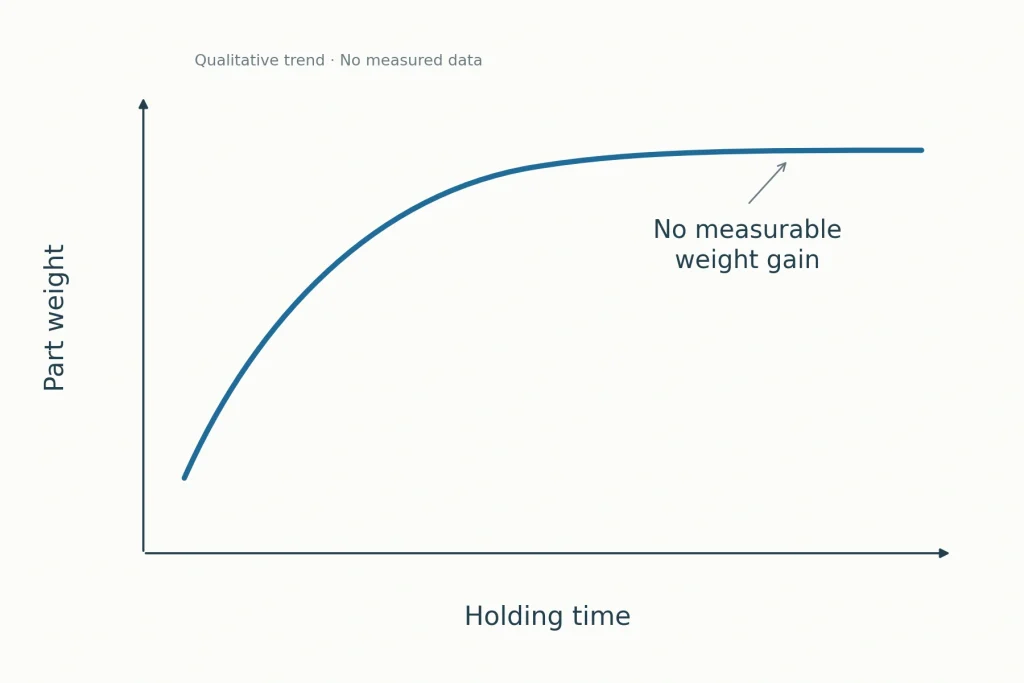
Judge the trend against sample variation and measurement resolution, not two identical displayed readings. If cavity-pressure sensors are available, interpret them according to their locations; a sensor near the gate does not directly measure conditions inside a remote boss.
Hot-runner and valve-gated systems require a method suited to their actual gate behavior and closing sequence. Do not assume that every system has the same thermal gate-seal event.
Reduce the Heavy Intersection Without Losing Its Function
When a sound process cannot provide an acceptable result, review the geometry feeding the sink.
For the example cover, possible revisions include coring the boss more effectively, separating it from a nearby sidewall, or replacing a bulky connection with suitable supporting ribs. Inspect the complete intersection after each change. A thin rib joined through an oversized root radius can still leave substantial local material.
There is no single rib-to-wall percentage that guarantees an invisible sink for every resin and finish. Use the selected material’s design guidance, then assess filling, strength, release, and appearance together.
Do not remove a boss-root radius simply to reduce material. That radius also affects stress concentration. Likewise, thinning a screw boss changes the material available to carry assembly loads. Confirm the screw or insert requirement and the intended tightening conditions before approving the revised section.
Draft changes the rib thickness along its height. A revision that reduces the base may leave a tip that is difficult to fill. The injection molding draft angle guide explains how to check the resulting dimensions rather than treating draft as a separate note.
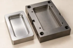
Tooling changes may also be appropriate. Gate size or location can improve access for packing, while cooling changes can address a persistent hot region. Review their effects on gate marks, flow-front meeting locations, release, and the rest of the part.
These options are alternatives to evaluate. None should be presented as a guaranteed correction without trial evidence from the revised design and process.
Approve the Surface and the Interior Against Their Own Requirements
Define what makes the sink unacceptable. A shallow depression on a decorative cover may be an appearance issue. A similar change on a sealing land, locating face, or label surface can have a different consequence.
For appearance, identify the inspection region, resin and color, lighting, viewing conditions, and approved boundary samples. If a numerical depth limit is required, define the reference surface and measurement method. A gloss difference alone is not a depth measurement.
The injection molding surface finish guide explains how to separate the mold’s finish designation from acceptance of the molded part. Changing texture may change visibility, but it does not restore the depressed geometry.
For a critical thick section, agree on the evidence needed to assess the interior. A prepared section through the suspect region can expose a void but destroys the sample and reveals only the section examined. CT may be useful where justified, provided its resolution and inspection coverage suit the defect being investigated. An internal cavity also needs diagnosis; trapped gas and shrinkage are not interchangeable explanations.
Use the appropriate assembly or load test when function matters. Neither a visible sink nor a clean surface, by itself, quantifies the component’s strength.
Keep the approved condition tied to the part revision, material, cavity, and process used to produce it. Compare samples after the agreed cooling or conditioning period, including any finishing that affects final acceptance.
For a recurring sink, share the marked surface location, a CAD section through the feature, the resin grade, and available holding-time or part-weight results. RapidEfficient can review the geometry, tooling questions, and sample-acceptance requirements through its injection molding services before the next tooling or production decision.