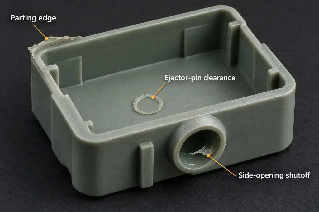
Injection molding flash is a thin fin or film of unwanted plastic that forms when molten resin enters a gap between mold components. It can appear along a parting line, around an insert, or at a vent or ejector-pin clearance.
The useful starting questions are where the plastic escaped and when the escape began. Those answers help separate a local sealing problem from a pressure, clamping, or filling problem.
A process change is successful only if it removes unacceptable flash while preserving the required fill, dimensions, and function. Trimming can be an approved finishing step, but it should not erase the evidence needed to understand a recurring defect.
Map the Flash to the Mold Interface
Keep several untrimmed samples and identify their cavity numbers and production sequence. Photograph the defect from a consistent direction with a scale, then mark its position on the part drawing. A close-up alone may hide whether the fin follows the main parting line or a separate insert joint.
Distinguish flash from other molding marks. A visible parting-line witness mark does not necessarily contain excess plastic. Misalignment between mold halves can create a step. A gate vestige is material remaining at the feed connection. These features may each need limits, but they do not point to the same corrective action.
Use the defect map to choose the first check:
| Flash pattern on the part | Mold interface or condition to investigate | Evidence to collect before changing settings |
|---|---|---|
| Flash along much of the main parting line | Mold closing, clamp load, support, and pressure during filling or packing | Whether several cavities are affected; pressure and transfer records; mold-contact and support checks |
| A fin at the same corner of one cavity | Local contact damage, contamination, wear, or uneven support | Repeated samples from that cavity and inspection of the matching steel surfaces |
| A ring around an ejector-pin position | Pin-to-bore clearance, wear, or local damage | The affected pin location and condition of both mating components |
| Flash around a side opening or molded-in insert | Slide or insert seating, shutoff contact, and dimensional variation | Seating checks and comparison with unaffected cavities or insert batches |
| A narrow tongue at a vent outlet | Vent depth, sealing-land condition, and suitability for the resin | Measured vent geometry, maintenance history, and the resin grade actually being molded |
These patterns guide investigation; none proves a cause by itself. One cavity can flash because of local damage, but differences in filling and packing can also expose its weakest sealing area.
Record the flash location before trimming changes the edge.
Read Pressure and Mold Fit Together
Resin can escape through a gap that already exists, or through one that opens under molding load. Both conditions can produce similar-looking flash.
An existing gap may come from worn contact surfaces, damaged steel, trapped material, or a component that does not seat correctly. A pressure-opened gap involves the response of the mold and clamping system to the load. Checking how the mold closes without injection does not establish how it behaves during filling.
BASF’s injection-molding troubleshooting guide identifies separate flash causes involving mold fit, damaged sealing surfaces, clamp force, cavity pressure, melt viscosity, and mold deformation. Its flash section is a useful starting point for separating those mechanisms.
For the clamp review, consider the total projected area of the cavities and relevant runner areas in the mold-opening direction, together with the pressure acting on them. Machine injection-pressure readings are not automatically the pressure at every point in the cavity. Mold stiffness, support, and load distribution also affect whether a local joint remains closed.
Increasing clamp force may help when available closing force is inadequate. It cannot restore a worn sealing surface. Review the machine and tool limits before changing clamp settings.
A vent requires a different judgment from an unintended gap. It provides an escape path for gas while restricting melt flow. Simply closing the vent to stop flash can create a filling problem elsewhere. Check its geometry and condition against the selected resin and mold design rather than applying one vent depth to every material.
Separate Filling from Packing
A finished part does not reveal exactly when its flash formed. The pressure history and controlled trial samples can help establish that timing.
During filling, resin advances through the cavity. In a conventional velocity-controlled cycle, velocity-to-pressure transfer changes control from filling to packing and holding. The later stage adds material and maintains pressure while the part cools and the gate remains able to transmit material.
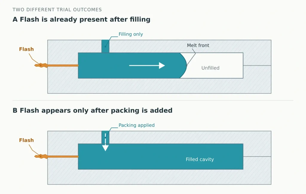
A process engineer can compare suitable filling-only trial samples with samples made using the normal packing stage. Keep the resin, mold condition, and intended filling profile controlled, and use a trial procedure that permits the incomplete parts to be removed safely.
If flash is already present on a filling-only sample, reducing holding pressure alone will not address its initial formation. Examine the affected interface, filling speed, transfer point, and pressure required to move the melt.
If flash appears only after packing is added, investigate the packing profile and the seal’s ability to withstand that load. This finding narrows the investigation; it does not prove that the tool is sound.
Make a controlled change and record its effect on both the flash and the rest of the part. Moving transfer earlier or lowering packing pressure may reduce the fin while producing an underpacked region, a sink, or a dimensional change.
Temperature adjustments also need a reason. A hotter, lower-viscosity melt may enter a small gap more readily. However, an excessively cold melt can require more pressure to fill the cavity. Follow the resin’s processing guidance and compare actual process behavior instead of treating “lower temperature” as a universal flash remedy.
The target is an acceptable filled part across a workable process window, not a clean edge on an underfilled sample.
When Flash and Short Shots Appear Together
Flash and incomplete filling are not mutually exclusive. Separate two situations: both defects on the same shot, and alternating defects on successive shots.
For example, a cavity may leak at a damaged edge while a distant thin feature remains incomplete. That is a diagnostic possibility, not proof that the visible gap is the only problem. Flow restrictions, venting, core movement, and pressure distribution may also need review.
Reducing the shot until the fin disappears can leave the distant feature even less complete. Increasing pressure to finish that feature may make the leakage worse. The trial needs to address the leaking interface and the difficult-to-fill region together.
Alternating flashing and short shots call for a repeatability check. Compare shot delivery, transfer behavior, cushion, and pressure records rather than assuming a fixed mold gap fully explains the variation. The screw cushion is commonly recorded as the distance between the screw’s forward position and its zero position, with melt remaining ahead of it. Compare readings taken at the same defined point in the cycle. Variation is a clue to investigate, not a diagnosis on its own.
Eastman’s troubleshooting guide for copolyesters explicitly separates flash and short shots in the same shot from those occurring in different shots. It directs attention to different checks, including core shift and delivery-system consistency. Apply its material-specific recommendations only where they fit the resin and equipment being used.
Define the Edge That Must Be Accepted
“Remove flash” leaves several questions unanswered. Which edge matters? How much residual projection is permitted? Can trimming alter the adjacent functional surface?
A fin on a hidden outside corner may have little effect on assembly. The same projection inside a connector opening can obstruct insertion. Loose flash near a fluid passage can become contamination. A trimmed sealing edge may look clean while its contact geometry has been damaged.
Define the affected region and the final condition in which it will be inspected. Where a numerical limit is necessary, identify the reference surface and measurement direction. Flash thickness, outward projection, and length along an edge are different quantities.
Select a measurement method that suits the fin. Contact measurement may bend a thin edge, so optical inspection can be useful when the contour must remain undisturbed. Access and resolution still need to match the feature and its specified limit.
Appearance requirements also need a viewing setup or an identified boundary sample. The injection molding surface finish guide explains how to define appearance zones and inspection conditions. A mold polish or texture grade does not establish a flash allowance.
If trimming is permitted, agree on the method and the surfaces it must preserve. Depending on the part, manual cutting, dedicated trimming, or another qualified removal process may be suitable. Check the resulting edge for remaining fins, loose fragments, gouges, and dimensional changes.
Trimming approval should cover the finished edge and any affected function, not only the removal of visible excess plastic.
Where sealing, sliding, or retention matters, include the relevant functional check. A visually acceptable edge cannot by itself establish leak tightness or assembly performance.
Confirm the Correction Across Cavities and Restarts
Keep the before-and-after samples tied to the change that produced them. Record whether the correction involved tool repair, vent work, material preparation, or a process adjustment.
Recheck the affected edge and the characteristics that could have changed with it. Lower packing pressure may affect dimensions. Tool work at a shutoff may alter the local contour. Trimming may change a mating edge.
For a multicavity mold, identify results by cavity rather than approving a mixed handful of good parts. Where startup or restart conditions contributed to the defect, include those conditions in the verification. One clean shot does not demonstrate repeatable control.
The first article inspection guide helps connect the drawing requirements with the agreed evidence package. Keep that product approval separate from any additional process-stability evidence the order requires.
For a part with recurring flash, send marked photographs of untrimmed samples, the resin grade, cavity identification, the affected assembly feature, and available process or tool-change records. Through our injection molding services, Rapid Efficient can review the defect location, tooling and process questions, permitted cleanup, and final acceptance requirements before quotation or further sampling.