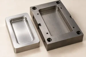
In injection molding, soft tooling often refers to aluminum molds used for prototypes, bridge production, or shorter production programs. Hard tooling usually refers to steel molds intended for longer service. These labels alone do not specify an alloy, hardness, mold construction, or production capacity.
Aluminum can be a practical choice when early delivery and limited initial investment matter, provided the tool suits the resin, geometry, and required output. It can produce end-use parts. Steel deserves closer consideration when repeated production, demanding working surfaces, or abrasive materials make durability more important.
The choice also includes prehardened steel and molds built from several materials. Before comparing prices, identify what forms the part, what is expected to wear, and what the buyer actually receives. Outside injection molding, “soft tooling” may describe other processes, including silicone molds; confirm that both quotations cover the same manufacturing route.
Separate the Mold Base from the Working Inserts
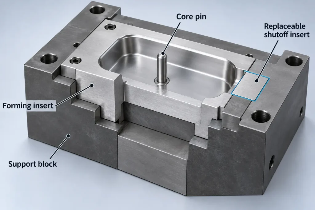
An injection mold is an assembly. The surrounding mold base, the cavity and core that form the part, and local components such as pins and sliding inserts can have different material requirements.
A steel base does not make an aluminum cavity a hardened steel cavity. Likewise, a mold with hardened working inserts does not need every supporting plate to have the same hardness.
Prehardened mold steel also matters in this comparison. It arrives in a heat-treated condition suitable for machining and use within its intended application. It is not simply untreated “soft steel,” and a later hardening operation is not automatically required.
Uddeholm’s guide to steel for plastic molding distinguishes prehardened, through-hardening, and corrosion-resistant mold steels. It also describes hardened cavity and core inserts supported in prehardened holder blocks.
Read the proposed construction by component:
| Mold component | What the quotation should identify | Why it changes the comparison |
|---|---|---|
| Cavity and core surfaces | Alloy or steel grade, supplied condition, and final hardness where applicable | These surfaces reproduce the part geometry and finish. “Steel mold” leaves their condition unclear. |
| Gates and shutoff faces | Material, surface treatment if specified, and whether the area is replaceable | Local damage or wear can affect filling, sealing, and flash before the rest of the tool needs replacement. |
| Core pins and moving inserts | Material, support, and replacement access | A small damaged component may stop production even when the main cavity remains usable. |
| Mold base and insert pockets | Base specification, insert fit, and included supporting components | Replacing an insert depends on its interfaces with the rest of the tool. |
Glass-filled resins can increase abrasive wear. Corrosion resistance is a separate selection issue. Neither requirement can be settled by a general “soft” or “hard” label.
Compare the specified working surfaces and their support, rather than assigning one material description to the whole mold.
Specify What a Mold-Life Claim Must Deliver
A mold-life statement needs a unit. A shot is one molding cycle; it is not necessarily one accepted part.
For a mold producing identical parts, an illustrative planning relationship is:
Required production shots = Required accepted parts ÷ (Active cavities × Expected yield)
Consider these assumptions, chosen only to demonstrate the calculation:
- The order requires 38,000 accepted parts.
- Two cavities produce the same part on every production shot.
- Expected yield during those production shots is 95%.
- An additional 500 trial and setup shots produce no parts counted toward the order.
Production shots = 38,000 ÷ (2 × 0.95) = 20,000
Total planned shots = 20,000 + 500 = 20,500
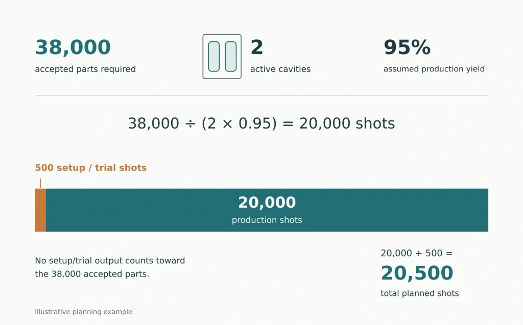
The 500 trial and setup shots are separate from the production-yield allowance. Counting those losses in both places would overstate the requirement.
This is a planning estimate, not a mold-life prediction. It assumes both cavities remain active and does not establish a maintenance interval or reserve capacity. A family mold producing different components needs a calculation for each required component; its cavities cannot simply be counted as interchangeable output.
State whether the quoted life refers to shots, molded pieces, or accepted parts—and what repairs are included.
The end point matters as much as the count. A mold may still cycle while producing unacceptable flash, worn texture, or dimensions outside the drawing limits. Agree on the part requirements that must remain satisfied, the approved resin, and the maintenance conditions behind the life claim.
Distinguish routine cleaning and servicing from replacing wear components or rebuilding a cavity. If cosmetic appearance affects acceptance, the injection molding surface finish guide explains why a mold finish designation alone does not define the finished part’s appearance.
Put Likely Design Changes into Replaceable Features
An early tool is often purchased while some dimensions remain open. “Easy to modify” should therefore refer to identified features, not just a softer mold material.
Suppose a housing’s mounting-hole position may change after assembly testing. A replaceable insert around that feature can provide a different revision route from a hole formed directly in a large core block. The insert still needs adequate support, suitable boundaries, and access for replacement.
A change that removes metal differs from one that requires metal to be restored. For example, enlarging a local cavity can increase the corresponding plastic volume. Reversing that change may require repair or a new insert. The effect depends on which mold surface controls the feature.
Before approving the tool layout, mark the features likely to change and ask which can be adjusted, which require replacement components, and which would affect gates, cooling, or ejection.
This review applies to aluminum and steel tooling. Faster machining does not make every aluminum-tool revision simple, and hardened steel does not make every revision impossible. The location and extent of the change matter.
Include the revised samples in the plan. A feature that can be changed mechanically still needs verification against the part drawing and assembly requirements.
Check Whether You Are Buying a Complete Mold
A tooling charge may cover cavity and core inserts used in a supplier’s existing frame. Another quotation may include a complete dedicated mold. These are different deliverables even if both produce the same part.
DME’s modular mold system documentation illustrates this distinction: interchangeable insert molds work within matching frames, allowing the frame to remain in the molding machine during an insert change.
For an insert-based quotation, ask which frame and related equipment are included. If future transfer matters, identify what would move with the project and what the receiving molder would need to supply.
Owning an insert does not establish that it can run in any mold base or press. Confirm the frame interface, ejection connections, runner arrangement, cooling connections, and receiving machine requirements before treating transfer as a ready backup plan.
The quotation should also identify the available tool drawings, material records, spare-component information, and maintenance history. These details help another toolmaker assess repair or reuse.
A low initial price may suit the project well. Its value depends on whether the included tooling and continued access to supporting equipment match the production plan.
Compare One Tool with a Planned Two-Tool Route
An aluminum bridge tool followed by a steel production tool can be a reasonable staged purchase. It also creates two tooling projects.
Compare the actual alternatives: one tool intended to cover the approved demand, or an early tool plus a later replacement. Include sampling, design revisions, maintenance, replacement inserts, and the approval work required when production moves.
There is no universal order quantity at which steel becomes the cheaper choice. The answer depends on the proposed construction, part geometry, resin, cavity count, usable output, and how long the design is expected to remain unchanged.
If the earlier decision is still whether to mold the part at all, the injection molding versus 3D printing comparison addresses that separate investment question.
For the tooling decision, compare the date of the first approved delivery and the ability to supply repeat orders. A shorter tool-machining schedule does not by itself establish either. Sampling, corrections, available press time, and part approval remain part of delivery.
A later production tool may use different gates, cooling, or cavity arrangements. Do not assume that approval of the bridge-tool parts automatically approves the replacement tool. Identify the dimensions, appearance, and functional tests affected by those differences. A first article inspection can document the new tool’s initial parts; continued production stability needs its own evidence.
For a tooling review, share the resin grade, expected accepted-part demand, likely design changes, and whether the tool must support future transfer. Include the proposed cavity count and any quoted life conditions. Rapid Efficient can review these requirements through its injection mold tooling service before the tooling scope is finalized.