
For a CNC wedge with a 45° seating face, the inspection scope depends on which requirement the supplier is quoting. An angle reading describes inclination. A surface-angularity result evaluates the face within a linear tolerance zone tied to the drawing’s datums. The difference affects the fixture, the measured area and the evidence delivered with the part.
In angularity GD&T, the basic angle sets the zone’s orientation; the tolerance value sets its width. On an inclined face, that width is measured perpendicular to the zone boundaries. Following this direction through a measurement example helps a buyer assess an inspection proposal and decide whether a reported failure needs further measurement or material removal.
Two Planes Define the Allowed Surface
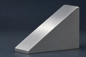
Consider a hypothetical rigid wedge with a planar base identified as datum feature A. Its seating face has a basic angle of 45° to datum A and a surface-angularity tolerance of 0.05 mm. A side datum B fixes the direction of the slope around A. Assume the drawing fully defines that orientation and uses an ordinary surface control without a tangent-plane modifier.
The angularity symbol is ∠. In a complete feature control frame, the symbol, tolerance and datum references work with the basic geometry and the attachment to the controlled face. Apply the standard and edition named on the drawing; these examples concern the actual seating surface, not the axis of an inclined hole.
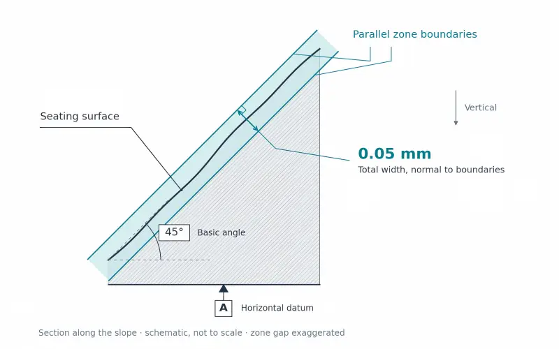
Two parallel planes, oriented at the specified basic angle, must enclose that surface. Their perpendicular separation may be no greater than 0.05 mm. The value is a total width, not ±0.05 mm and not 0.05°. KEYENCE’s orientation-tolerance guide illustrates this two-plane interpretation for an inclined surface.
The enclosing planes retain the required orientation while their position is fitted to the surface for this angularity evaluation. A separate dimension or geometric control must establish where the seating face belongs in the assembly. Moving an otherwise identical face inward can preserve its angularity while changing the wedge’s height.
The neighboring perpendicularity guide addresses the 90° case and the distinction between surface and axis controls. Here, the additional practical issue is how measurements taken vertically relate to an inclined tolerance zone.
Vertical Departures Need a Direction Correction
Keep datum A horizontal and consider a section along the wedge’s slope. Choose a reference plane at exactly 45°, with the required orientation to A and B. At each measured horizontal position, calculate the vertical difference between the actual point and that reference plane. Call this difference e.
These differences are not the raw heights of the face. Raw heights rise along the intended slope even on a perfect wedge. The reference plane removes that nominal rise, while preserving the specified orientation.
For this geometry, the signed perpendicular distance d from a point to the reference plane is:
d = e × cos 45°
The projection preserves the sign of e. The magnitude of d is the shortest distance to the reference plane, measured at a right angle to that plane. With the zone orientation fixed, the required enclosing width for the sampled points is:
T = largest d − smallest d
The following values are invented teaching data, in millimeters. Four points demonstrate the arithmetic; they are not a sufficient inspection plan for an entire seating face.
| Sample point | Vertical departure e from the 45° reference plane | Perpendicular distance d |
|---|---|---|
| P1 | −0.020 | −0.01414 |
| P2 | 0.000 | 0.00000 |
| P3 | +0.040 | +0.02828 |
| P4 | +0.060 | +0.04243 |
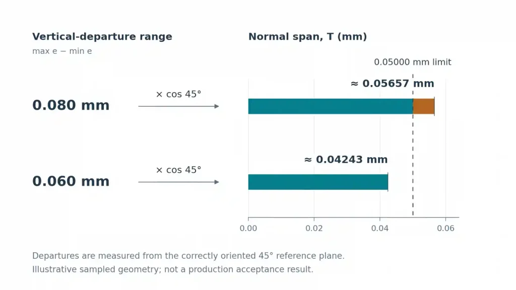
Using unrounded values, T = 0.080 × cos 45° = approximately 0.05657 mm. That exceeds the illustrative 0.05 mm zone width. Comparing the vertical range of 0.080 mm directly with the drawing’s 0.05 mm would use the wrong measuring direction, even though both comparisons happen to reject this example.
The distinction can also change the outcome. Consider a different set of sampled points with a vertical-departure range of 0.060 mm. Its normal span across the same inclined zone would be approximately 0.04243 mm. This set would fit geometrically within 0.05 mm; a direct comparison using 0.060 mm would reject it. Production acceptance still requires adequate surface coverage and the applicable measurement decision rule.
This cosine calculation applies to vertical departures from a correctly oriented reference plane in the stated geometry. It is not a universal correction for an indicator reading. Instrument contact geometry, part alignment and the direction represented by the reported data must all be known.
An angle reading needs a different calculation. For a perfectly planar face of length L measured along the face in the tilt direction, an orientation error Δθ produces a normal span of L × sin |Δθ|. With no other form error or transverse tilt, a 40 mm face tilted by 0.10° requires about 0.06981 mm; a 10 mm face with the same tilt requires about 0.01745 mm. The same angular error therefore has different consequences over different face lengths. Bowing or twist requires evaluation of the actual surface rather than this ideal-plane calculation.
Build the Inspection Around the Zone Normal
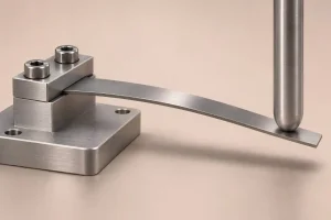
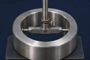
One physical inspection route uses an angular fixture to orient the wedge so that the nominal seating face is parallel to the inspection surface plate. The fixture must establish the drawing datums and the specified angle. A suitable indicator arrangement can then measure departures in the direction normal to the nominal seating face.
Set that orientation from the basic geometry. Tilting the fixture until the actual face produces the smallest sweep would remove some of the orientation error being inspected. Check datum seating, fixture accuracy, instrument response and restraint as part of the method. Traverse the controlled area in both directions; a single line along the slope can miss variation across the width.
A CMM can perform the corresponding evaluation from surface data and the specified datum alignment. Keep the nominal orientation constrained as required by the drawing. The result should retain the surface’s departure from that orientation, including its form, rather than report only the angle between fitted planes.
Hexagon’s PC-DMIS angularity documentation describes evaluation through the smallest enclosing zone under the datum constraints. Its example also shows how sparse sampling can underestimate the zone width needed to enclose the actual surface. A successful software calculation therefore still needs a measurement strategy suited to the face.
For this wedge, the inspection deliverable should identify the controlled face, A–B alignment, evaluated area and angularity value in millimeters. Retain the separate face-location result where the drawing requires one. If the report gives a vertical range or an angle instead, resolve what that number represents before accepting it as angularity.
When comparing CNC machining proposals, include the required angular setup and surface evaluation in the quoted inspection scope. A price for checking a single angle covers a different task from evaluating the specified seating face against its two-plane zone.
Recutting the Slope Changes Where the Face Sits
A confirmed failure leads to a material-removal decision. Changing the machining-fixture angle before a new cut may correct an orientation error, while a bowed or locally damaged face also needs enough removal to clean up its form. The proposed finished plane has to fit inside the material that remains.
Return to the wedge’s assembly dimensions before approving that cut. Removing stock from the seating face changes its position relative to the base, nearby holes and stops. If a recess opens onto the face, cutting the face farther inward also changes the recess depth measured from it. Good angularity after rework can therefore accompany an unacceptable contact height or recess depth.
Ask for the proposed finished plane to be shown on a section of the current part, with the affected dimensions recalculated. Where the drawing permits the new position, the reworked face can be inspected for both its orientation and its remaining dimensional requirements. Where the necessary cut crosses a dimensional limit, stop the proposed rework and refer the part for an approved disposition, such as a design concession or replacement.