Quick Answer
RapidEfficient machined an aluminum bearing housing with a selected bore size tolerance of ±0.005 mm. We treated the bore as a dedicated critical feature rather than applying the same tolerance across the entire part. The process separated roughing from final bore sizing and coordinated stable references, low-distortion workholding, tool-condition control, post-unclamp stabilization, and feature-specific inspection.
Project Overview
The customer required a CNC-machined aluminum bearing housing with one bore held within a narrow size range. The surrounding mounting and clearance features did not require the same tolerance level.
| Project Item | Requirement |
|---|---|
| Component | CNC-machined aluminum bearing housing |
| Material | Aluminum alloy specified for the project |
| Critical feature | Selected bearing bore |
| Bore size tolerance | ±0.005 mm |
| Total size window | 0.010 mm |
| Functional priority | Bearing fit, bore stability and repeatable inspection |
| Main manufacturing risks | Clamping distortion, tool wear, heat, bore geometry and inspection uncertainty |
| Process route | Staged machining, dedicated bore finishing and feature-specific inspection |
A tolerance of ±0.005 mm means that the upper and lower size limits are each 0.005 mm from nominal. The complete allowable size window is therefore 0.010 mm.
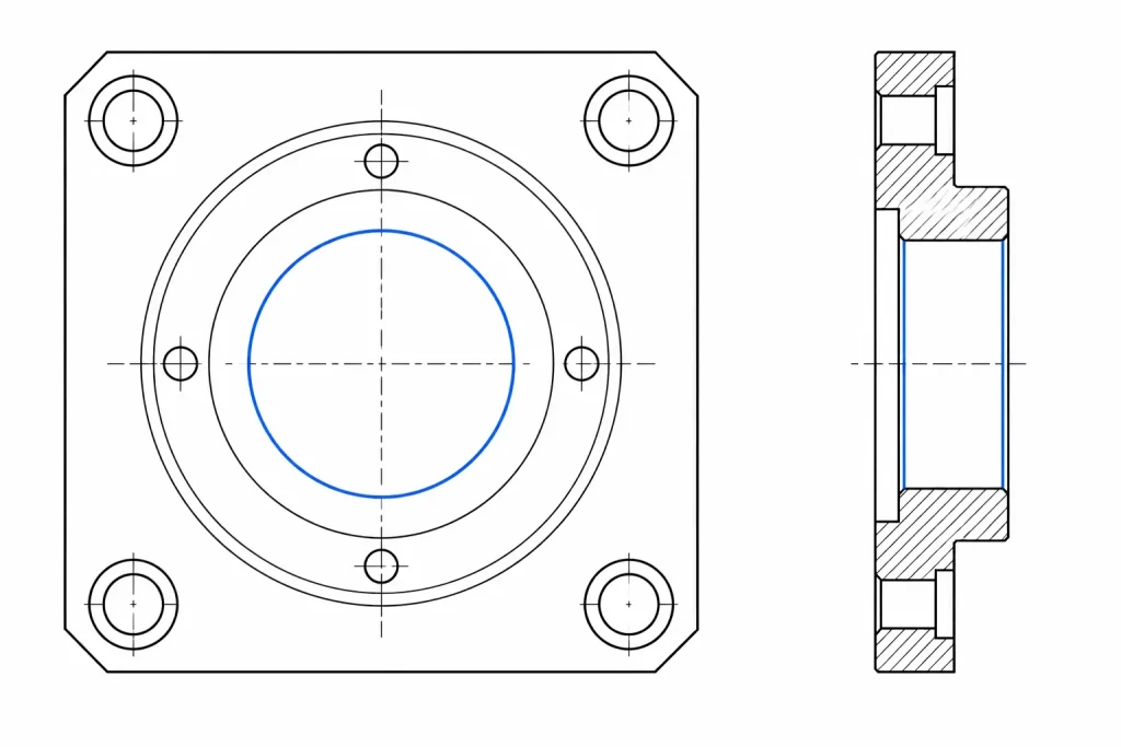
This distinction matters. Describing the requirement only as “five-micron precision” can incorrectly suggest that the complete size window is 0.005 mm.
To protect customer confidentiality, identifying information and selected project dimensions are not disclosed.
For broader feature-level tolerance planning, review our CNC aluminum tolerance guide.
Bore Size Alone Did Not Define the Fit
A bearing bore cannot be accepted only because one diameter reading falls inside the size limits.
Its function may also depend on:
- Roundness
- Cylindricity
- Bore taper
- Surface texture
- Burr condition
- Relationship to the mounting face
- Relationship to another bore or shaft axis
- Final condition after unclamping
- Whether the dimension applies before or after surface treatment
Size tolerance and geometric control are separate requirements.
If axis alignment, runout, position, roundness or cylindricity affects the assembly, the drawing must define the required control, datum structure and inspection basis.
Not every bearing housing needs all these specifications. They should be added only when they protect bearing fit, alignment, motion or service life.
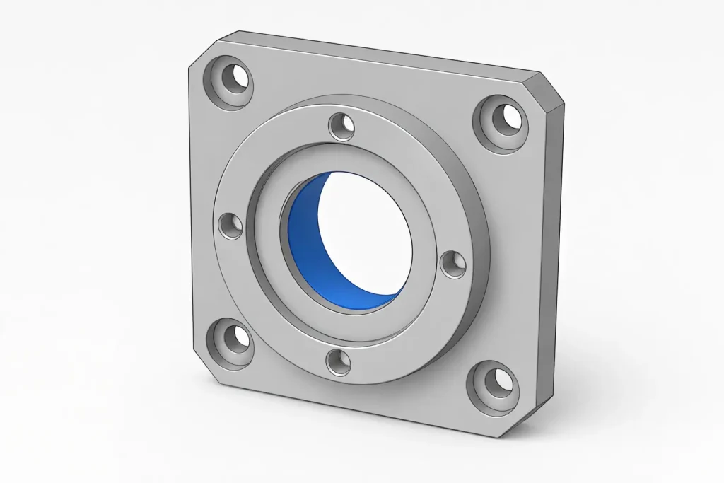
We Defined the Fit Before Finalizing the Process
Before planning the final bore operation, we reviewed how the bore connected to the mating component.
The review considered:
- The bearing or sleeve fitted inside the bore
- The nominal bore size and allowable limits
- Whether the bearing outer ring needed to remain fixed or permit movement
- The functional mounting reference
- Relevant surface-texture requirements
- Burr and edge-break requirements
- Whether dimensions applied before or after anodizing or another coating
- The required inspection method and documentation
- Whether operating temperature could affect the final fit
A narrow machining tolerance cannot compensate for an undefined fit.
If the mating relationship is still being developed, our press-fit tolerance guide explains how interference, clearance, material behavior and inspection requirements should be separated before production.
Why the Aluminum Housing Needed a Controlled Sequence
Aluminum is machinable, but good machinability does not automatically produce a stable bearing bore.
The housing could still change because of:
- Residual stress released during material removal
- Uneven roughing around the bore
- Clamping pressure
- Cutting force near the final wall
- Tool runout or deflection
- Cutting-edge wear
- Chips recutting the bore surface
- Temperature differences between machining and inspection
- Burrs at the bore entrance or exit
- Part movement after the fixture was released
These risks became more important because the critical bore had to remain stable in the delivered, unclamped condition.
We therefore treated the bore as a separate manufacturing and inspection stage rather than expecting the roughing operation to produce the final accepted feature.
Machining Route for the Critical Bore
1. We Established a Stable Manufacturing Reference
The early operations established a broad support face and the main locating features required for later setups.
This gave the fixture a repeatable contact condition and reduced the risk of locating the housing against:
- An unfinished surface
- A burred edge
- A small unstable contact point
- A surface that could move under clamping force
The manufacturing reference also supported the inspection plan. The part needed to be machined and inspected from references that represented its functional mounting condition.
2. We Removed the Main Stock Before Final Bore Sizing
We roughed the main pockets and surrounding geometry before completing the critical bore.
Controlled finishing stock was left on the bore so that the final operation did not have to correct:
- Deep roughing marks
- Uneven remaining material
- Interrupted stock
- Local distortion caused by heavy material removal
- Tool-load changes from nearby features
The appropriate finishing allowance depends on bore size, depth, wall thickness, tool, material condition and machine setup. It should not be copied as one fixed value between different components.
3. We Checked Stability After Roughing
After the main material removal, we checked that the housing remained suitable for final machining.
The review included:
- Verifying that the part seated consistently
- Checking the main support condition
- Confirming that sufficient finishing allowance remained
- Looking for visible movement around the bore
- Checking that chips or burrs did not affect relocation
- Allowing the part to reach a stable condition before final inspection
A mandatory waiting period is not required for every aluminum component. It is used only when the stock condition, geometry or observed movement justifies it.
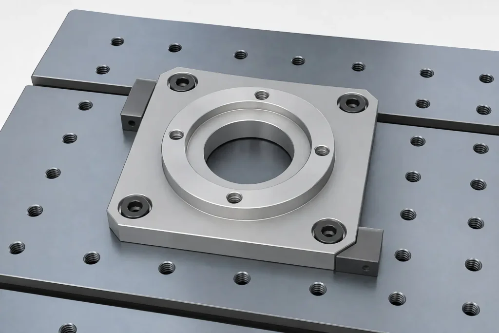
4. We Used Low-Distortion Workholding
The fixture had to locate the housing repeatably without forcing the critical bore into shape.
The workholding strategy focused on:
- Broad support close to the functional region
- Clean and burr-free locating surfaces
- Controlled clamping force
- Repeatable seating
- Access for the final bore tool
- Clearance around the critical feature
- Inspection after the part was released
The objective was not simply to hold the part firmly. It was to hold the housing without introducing a temporary shape that disappeared after unclamping.
A bore that measures correctly only while restrained has not yet demonstrated its delivered condition.
5. We Kept Final Bore Sizing Separate from Roughing
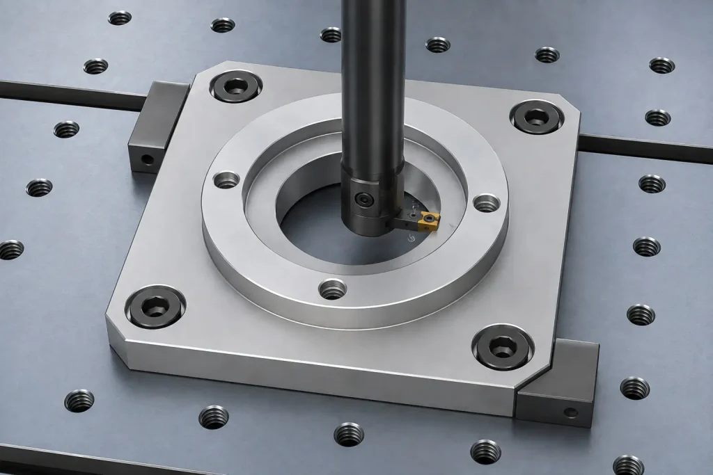
The critical bore was completed in a dedicated finishing stage.
The finishing operation was selected according to:
- Bore diameter and depth
- Required surface texture
- Wall rigidity
- Tool access
- Remaining stock
- Adjustment capability
- Inspection method
- Production requirements
Depending on the feature, a suitable route may involve precision boring, controlled circular interpolation, reaming or another qualified finishing method.
For this project, the important process decision was to protect the bore from roughing-tool load and complete its final size only after the surrounding geometry and setup condition had been stabilized.
The final tool and cutting parameters were selected for the actual machine, holder, feature geometry and stock condition. They should not be transferred directly to another project without review.
6. We Controlled Tool Condition and Final Entry
A narrow bore tolerance can be lost gradually as the finishing edge wears.
The process therefore controlled:
- Tool runout
- Cutting-edge condition
- Tool projection
- Entry into the bore
- Chip evacuation
- Finishing-stock consistency
- Tool-compensation limits
- Replacement or adjustment triggers
Tool compensation is useful when it corrects a predictable process trend. It should not be used to hide unstable workholding, built-up edge, damaged tooling or inconsistent remaining stock.
7. We Deburred Without Changing the Functional Edge
The bore entrance and exit required controlled deburring.
Aggressive hand finishing can enlarge the edge, create an uncontrolled chamfer or damage the bearing contact region.
The drawing and process therefore needed to distinguish between:
- Burr removal only
- A controlled edge break
- A specified chamfer
- A specified radius
- A protected functional edge
The deburring method had to protect the bearing fit rather than merely improve appearance.
Inspection Had to Match the Feature
We inspected the critical bore after the part was released from the fixture.
The inspection method had to resolve the 0.010 mm total size window with suitable repeatability and measurement capability.
CMM inspection can be valuable, but it is not automatically the only or best method for every precision bore.
| Feature or Relationship | Possible Inspection Method | Main Purpose |
|---|---|---|
| Bore size | Bore gauge, air gauge or suitable CMM strategy | Confirm the dimensional size limits |
| Bore taper | Measurements at controlled depths or scanning | Check whether bore size changes along its length |
| Roundness or cylindricity | CMM scanning or suitable form-measurement equipment | Evaluate bore form when required |
| Bore axis to mounting reference | CMM or another datum-based inspection method | Check the functional geometric relationship |
| Mounting-face flatness | Suitable CMM, surface-plate or form-inspection method | Confirm the support condition |
| Surface roughness | Profilometer using an agreed measurement direction and cutoff | Verify texture when specified |
| Burr and edge condition | Magnified visual or tactile inspection under an agreed standard | Protect fit, assembly and handling |
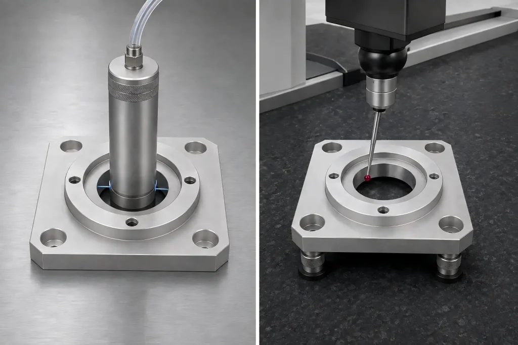
The selected method depends on feature access, drawing requirements, measurement uncertainty, report expectations and available inspection capability.
Bore size and bore-to-datum relationships may also require different inspection methods. One instrument does not need to perform every acceptance check.
For a broader explanation of tolerance budgeting and inspection planning, see our CNC machining tolerances guide.
We Controlled the Final Inspection Condition
A warm part and a cooler measuring instrument do not represent the same dimensional condition.
Before final acceptance, we considered:
- Cutting heat
- Coolant condition
- Part handling
- Time between machining and inspection
- Part and gauge temperature
- Measurement-room conditions
- The reference condition defined by the drawing or inspection agreement
This does not mean every precision aluminum housing requires one universal workshop temperature range.
It means the workpiece and inspection equipment must reach a sufficiently stable and agreed condition when temperature differences could affect the acceptance decision.
The bore also needed to be inspected in its delivered mechanical condition. Measuring it only while clamped would not confirm its size and geometry after release.
From First Article to Repeat Production
An acceptable first housing confirmed that the initial process route could produce the required feature. Repeat production also required the process to remain stable as tools, setups and inspection conditions changed.
The control plan included:
- First-article verification of the bore and related references.
- Inspection after the housing was released from the fixture.
- In-process bore checks at an agreed frequency.
- Monitoring of tool condition and adjustment history.
- Reverification after tool replacement or fixture disturbance.
- Review of bore surface and burr condition.
- Final inspection records according to the drawing or purchase order.
- Revision control for the drawing, model and inspection plan.
Prototype, low-volume and repeat-production orders may use different inspection frequencies. The required evidence should be agreed before production.
For projects requiring formal dimensional documentation, review our guide to first article inspection.
Project Outcome and Applicable Boundary
The bearing housing was completed using separate roughing, final-bore sizing and post-unclamp inspection stages.
The critical bore was inspected against the agreed drawing requirement before the part was released for delivery.
This case shows why a selected ±0.005 mm bore must be supported by:
- Stable manufacturing references
- Controlled stock removal
- Low-distortion workholding
- A dedicated finishing stage
- Tool-condition control
- Stable inspection conditions
- A measurement method matched to the feature
It should not be interpreted as a general ±0.005 mm tolerance for every dimension on an aluminum component.
Feasibility still depends on:
- Feature size
- Bore depth
- Material and stock condition
- Wall thickness
- Datum structure
- Machining access
- Workholding
- Surface treatment
- Quantity
- Inspection capability
- Final operating condition
Buyer Checklist for a Precision Aluminum Bearing Housing
Before requesting quotation, provide:
- 2D drawing and 3D model
- Aluminum grade and temper
- Nominal bore size and allowable limits
- Bearing or mating-component specification
- Required fit or assembly condition
- Datum references
- Roundness, cylindricity, runout or position requirements where functional
- Surface-roughness requirement
- Burr and edge-break notes
- Wall thickness around the bore
- Surface treatment and masking requirements
- Whether dimensions apply before or after finishing
- Prototype and production quantity
- Inspection method or report requirement
- Operating-temperature information when relevant
Do not apply ±0.005 mm to every feature unless the function genuinely requires it. Identify the bearing seat, alignment feature or mating interface that controls assembly performance.
Send Your Bearing Housing for Tolerance Review
If your aluminum bearing housing includes a critical bore, bearing seat, mounting face or bore-to-datum relationship, send RapidEfficient the 2D drawing, 3D model, material requirement, mating-component information, quantity and inspection expectations.
We can review whether the selected tolerance is compatible with the part geometry, machining route, workholding, finishing condition and measurement method before quotation.
Learn more about our precision machining support or send the project files for review.