CNC aluminum tolerance should be selected by feature and function, not by applying one tight number to the entire drawing.
A general outside dimension, precision bearing bore, thin wall, large plate, datum-related hole pattern, and anodized thread do not create the same manufacturing or inspection risk.
For many non-critical machined dimensions, a supplier may work with a general shop tolerance near ±0.10 mm or ±0.005 in unless the drawing says otherwise. That is not a universal aluminum standard or a guaranteed capability for every feature.
Selected aluminum features may require substantially tighter control, but the supplier must first review:
- Feature size and depth
- Aluminum alloy and temper
- Stock form
- Wall thickness
- Tool access
- Number of setups
- Datum structure
- Surface treatment
- Quantity
- Final inspection method
- Whether the requirement applies before or after finishing
A tolerance such as ±0.005 mm may be possible on a selected, accessible feature under controlled conditions. It should not be treated as a standard capability for every dimension on an aluminum part.
For broader, material-independent tolerance planning, review our existing CNC machining tolerances guide.
Why One Tolerance Number Is Not Enough
A tolerance chart becomes misleading when it presents one number as equally achievable across every feature.
For example, the same ±0.02 mm requirement may apply to:
- A shallow 10 mm bore
- A 300 mm overall length
- A deep internal pocket
- A thin flexible wall
- A multi-face hole pattern
- A feature that must remain controlled after anodizing
These features require different tools, setups, workholding methods, thermal conditions, and inspection equipment.
Tolerance difficulty also changes with:
- Feature accessibility
- Tool length-to-diameter ratio
- Part rigidity
- Material removal percentage
- Fixture repeatability
- Surface roughness
- Burr sensitivity
- Measurement uncertainty
- Batch size
- Part temperature during inspection
A useful chart should therefore describe how each feature must be controlled, rather than promising the same precision across the entire part. This feature-level approach also separates the page from the broader close tolerance machining guide, which covers multiple materials and general close-tolerance planning.
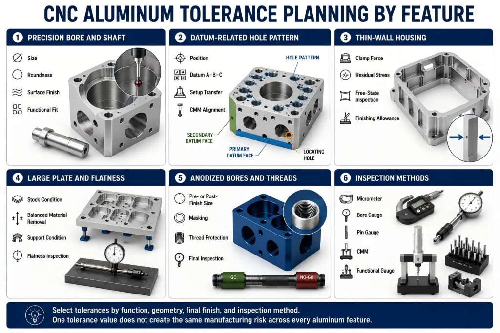
CNC Aluminum Tolerance Planning Chart by Feature
The following table is a drawing and RFQ planning guide, not a universal capability guarantee.
| Aluminum feature | Practical tolerance approach | Main manufacturing risks | Inspection considerations |
|---|---|---|---|
| General outside profile | Use the drawing’s general tolerance unless function requires more | Tool deflection, setup transfer, burrs | Caliper, micrometer, CMM, or profile inspection |
| Pocket length or width | Specify individually when it locates another component | Corner engagement, tool wear, measurement access | Caliper, micrometer, gauge, or CMM |
| Pocket depth or step height | Control where seating or assembly depends on depth | Datum condition, tool length, chip accumulation | Depth micrometer, height gauge, or CMM |
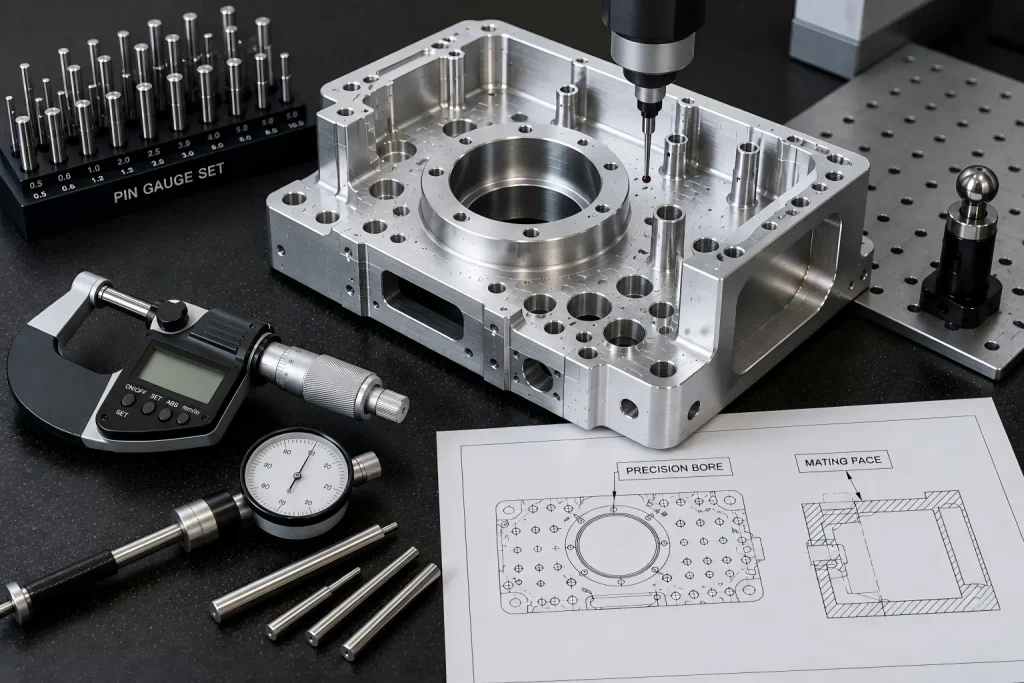
| Precision bore | Use explicit limits or an approved fit designation | Tool wear, roundness, depth, heat, surface finish | Bore gauge, plug gauge, air gauge, or CMM |
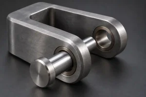
| Fitted shaft or boss | Use explicit limits based on the mating component | Tool wear, thermal condition, surface texture | Micrometer, snap gauge, or functional gauge |
| Hole pattern | Use position relative to clear datums | Setup alignment, datum transfer, fixture repeatability | CMM or an agreed inspection fixture |
| Mating face | Use flatness, parallelism, or perpendicularity where required | Clamping, stress release, large-area finishing | Surface plate, height gauge, CMM, or optical method |
| Thin wall | Confirm tolerance after unclamping and in the required state | Clamp force, cutting force, residual stress, spring-back | CMM, optical method, fixture check, or free-state measurement |
| Large plate | Specify flatness over the defined area and support condition | Stock flatness, one-sided removal, temperature, gravity | Surface plate, CMM, straightedge, or optical inspection |
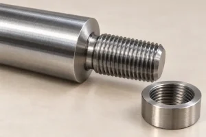
| Internal thread | Define thread class and final finishing condition | Burrs, anodizing, masking, gauge access | GO/NO-GO thread gauge |
| Anodized bore or shaft | State whether final size applies before or after anodizing | Surface conversion, masking variation, post-finish handling | Bore gauge, pin gauge, micrometer, or functional fit |
| Cosmetic surface | Control appearance and roughness separately from dimensional tolerance | Tool marks, handling, blasting, anodizing variation | Visual standard, roughness tester, approved sample |
The table should be used to start a supplier review. Final limits depend on the complete drawing, alloy, stock, geometry, finishing route, quantity, and inspection requirement.
General Tolerances, Critical Features, and ISO 2768
A drawing should distinguish between dimensions that can follow a general tolerance note and features requiring individual control.
General Tolerances
General tolerances are appropriate for dimensions such as:
- Non-critical outside profiles
- Clearance pockets
- Cover dimensions
- Chamfers without a fit function
- Cosmetic boundaries
- Non-locating clearance holes
- Features with generous assembly clearance
These dimensions should still be manufacturable, measurable, and consistent, but they do not normally need the same control as a bearing seat or locating bore.
Individually Specified Tolerances
Use an individual dimensional or geometric tolerance when a feature controls:
- Press fit
- Slip fit
- Bearing installation
- Shaft alignment
- Sealing
- Motion
- Optical or sensor position
- Mating-part location
- Assembly stack-up
- Post-finish size
- Functional inspection
Applying close tolerances only to critical features normally produces a more useful drawing than setting every dimension to ±0.01 mm.
Where ISO 2768 Fits
ISO 2768-1 provides general tolerances for linear and angular dimensions that do not have individual tolerance indications. It uses the classes fine, medium, coarse, and very coarse. The intended class must be stated on the drawing; ISO 2768 should not be treated as an unnamed default shop capability.
The old ISO 2768-2 standard for general geometrical tolerances has been withdrawn. Geometric requirements such as flatness, parallelism, perpendicularity, position, profile, and runout should be defined using the applicable drawing and GD&T framework instead of relying on an unclear general note. ISO 1101:2017 remains a published standard covering tolerances of form, orientation, location, and runout.
For holes and shafts requiring a controlled fit, ISO 286 provides a standardized code system for linear sizes, tolerance classes, deviations, and fits. The fit designation should be selected from the actual assembly requirement rather than copied from an unrelated project.
A drawing note such as ISO 2768-m does not replace individual control of:
- Bearing bores
- Press-fit shafts
- Datum-related hole patterns
- Sealing faces
- Precision alignment features
- Post-anodize dimensions
- Critical flatness or position requirements
Three Aluminum Features That Need Different Tolerance Strategies
A precision bore, a datum-related hole pattern, and a flexible aluminum structure may show similar numerical tolerances on a drawing, but they require different machining and inspection strategies.
Precision Bores, Shafts, and Fits
Precision bores and shafts should be reviewed as complete functional features.
The nominal diameter and size tolerance are only part of the requirement. Performance may also depend on:
- Roundness
- Cylindricity
- Straightness
- Surface roughness
- Bore depth
- Edge condition
- Taper
- Datum orientation
- Part temperature
- Mating-component tolerance
- Final surface treatment
A shallow, accessible bore in a rigid block is usually easier to control than a deep bore through a thin wall or a bore machined across multiple setups.
Questions to Confirm Before Quotation
- Is the feature a press fit, slip fit, clearance fit, or bearing seat?
- What is the mating component?
- Does the specified size apply before or after anodizing?
- Is masking allowed?
- Are roundness or cylindricity functionally important?
- What surface roughness is required?
- Is 100% gauging required?
- Is a numerical inspection report required?
- Will the buyer provide a master or mating component?
Do not specify a narrow diameter tolerance without also checking whether the surface condition and geometric form can support the required fit.
Hole Position, Datums, and GD&T
Hole size and hole position are different requirements.
Hole diameter may depend on:
- Tool diameter and wear
- Bore depth
- Material adhesion
- Surface finish
- Roundness
- Burrs
- Inspection method
Hole position may depend on:
- Datum selection
- Fixture repeatability
- Number of setups
- Machine alignment
- Feature spacing
- Part deformation
- Datum transfer
- Inspection alignment
For functional hole patterns, datum-based position control is often clearer than giving separate ± coordinate tolerances from several edges.
A useful drawing identifies:
- Primary datum
- Secondary datum
- Tertiary datum
- Controlled hole pattern
- Basic dimensions
- Position tolerance
- Material condition modifier where appropriate
- Inspection basis
- Final machined or finished condition
Clear datum selection connects the machining setup, drawing requirement, assembly function, and inspection report. For more examples, see our CNC machining datums guide.
Thin-Wall Aluminum Tolerances
Thin-wall aluminum parts may move during machining, after unclamping, during deburring, or after surface finishing.
The part can measure correctly while restrained and change after it is released.
Common risk factors include:
- Excessive clamp force
- Small jaw contact area
- High cutting force
- Uneven wall thickness
- One-sided material removal
- Residual stress in the stock
- Heat accumulation
- Tall unsupported walls
- Long finishing tools
- Inconsistent inspection pressure
For a thin-wall requirement, the drawing or RFQ should state:
- Nominal wall thickness
- Tolerance
- Unsupported wall height
- Critical area
- Datum reference
- Free-state or restrained inspection
- Final surface treatment
- Quantity
- Inspection method
Possible process controls include distributed support, purpose-built soft jaws, staged roughing and finishing, balanced stock removal, controlled finishing allowance, and inspection after unclamping.
These controls may reduce risk, but no single fixture or machining sequence is appropriate for every thin-wall aluminum housing.
Large Plates and Flatness
Large aluminum plates create a different problem from small precision bores.
Flatness may be affected by:
- Incoming stock condition
- Plate temper
- One-sided material removal
- Pocket depth
- Material removal percentage
- Clamping sequence
- Residual stress
- Cutting heat
- Part support during inspection
- Gravity and orientation
A flatness callout should define the controlled surface and relevant inspection condition.
Avoid using a small bilateral thickness tolerance as a substitute for flatness. A plate may have the correct thickness at several points but still be bowed or twisted.
For large plates, the supplier may need to review:
- Stress-relieved plate or cast tooling plate
- Balanced material removal
- Multiple roughing stages
- Rest periods between operations
- Support during final machining
- Support during inspection
- Whether flatness applies before or after surface treatment
6061, 7075, 5052, and Stock-Form Differences
There is no simple ranking in which one aluminum alloy always holds tighter tolerances than another.
Tolerance stability depends on the exact combination of:
- Alloy
- Temper
- Plate, bar, extrusion, sheet, forging, or cast stock
- Part size
- Wall thickness
- Material direction
- Residual stress
- Machining sequence
- Removed material volume
- Final finish
| Aluminum option | Practical tolerance considerations |
|---|---|
| 6061-T6 | Widely available and practical for many machined parts, but geometry and stock form still control distortion risk |
| 6061-T651 | Commonly considered for machined plate components where stress-relieved stock is useful |
| 7075-T6 or T651 | Higher strength and rigidity can help some features, but residual stress, corrosion requirements, tooling, and cost still require review |
| 5052-H32 or H34 | Often selected for formed sheet parts; its softer, more ductile cutting behavior may increase burr and surface-finish risk during extensive machining |
| Extruded aluminum | Grain direction, profile variation, straightness, and wall consistency may affect final machining |
| Cast tooling plate | Useful for some large flat plates and fixtures, but brand, porosity, strength, thread requirements, and finish must be reviewed |
The comparison must be made between specific tempers and stock forms—not only between alloy numbers.
For a detailed material comparison, see our 5052 vs 6061 aluminum guide.
How Anodizing Affects Aluminum Tolerances
Anodizing converts the aluminum surface into an oxide layer and changes the final dimensions of affected features.
The dimensional effect depends on:
- Alloy
- Anodizing type
- Required oxide thickness
- Geometry
- Process control
- Masking
- Racking
- Surface preparation
- Whether the feature is measured before or after finishing
Features requiring special attention include:
- Bearing seats
- Precision bores
- Fitted shafts
- Internal threads
- External threads
- Sliding interfaces
- Press-fit features
- Electrical contact areas
- Grounding surfaces
- Sealing faces
The Drawing Should State
- Whether the tolerance applies before or after anodizing
- Which areas require masking
- Whether threaded features must be protected
- Whether post-anodize inspection is required
- Whether a functional gauge or mating-part check is required
- Whether touch-up or post-machining is allowed
- Which surfaces are cosmetic
A drawing that says only black anodize may not provide enough information for a close-tolerance assembly.
For finish defects, masking risks, thread issues, rack marks, stains, and dimensional review, see our aluminum anodizing defects guide.
Inspection Method by Aluminum Feature
A tight tolerance is useful only when the feature can be inspected with an appropriate method.
| Feature | Possible inspection method |
|---|---|
| Outside diameter or width | Micrometer, caliper, snap gauge |
| Precision bore | Bore gauge, plug gauge, pin gauge, air gauge |
| Hole position | CMM or agreed inspection fixture |
| Flatness | Surface plate, height gauge, CMM, optical method |
| Parallelism or perpendicularity | CMM, height gauge, surface plate setup |
| Small slot | Pin gauge, optical inspection, CMM |
| Thread | GO/NO-GO thread gauge |
| Surface roughness | Roughness tester |
| Thin flexible wall | CMM, optical inspection, fixture check, or agreed free-state method |
| Assembly interface | Functional gauge or mating-part check |
| Anodized fitted feature | Post-finish gauge, dimensional inspection, or functional fit check |
A CMM is useful for many positional, profile, and datum-related requirements, but it is not automatically the best tool for every diameter, thread, or fit.
Inspection planning should also consider:
- Instrument resolution
- Calibration status
- Measurement uncertainty
- Feature access
- Part temperature
- Part cleanliness
- Burr condition
- Free or restrained state
- Sampling plan
- Report format
For report structure, datum alignment, measured points, sampling, and buyer review, see our CMM inspection for CNC parts guide.
What Makes CNC Aluminum Tolerances More Expensive?
Cost does not increase according to tolerance width alone.
A selected ±0.02 mm bore may be straightforward, while a large thin housing with ±0.10 mm flatness may require more workholding, roughing stages, stabilization, and inspection.
| Cost driver | Why it can increase cost |
|---|---|
| Tight tolerance on only a few accessible features | Usually easier to isolate and control |
| Tight tolerance applied across the entire drawing | More machining and inspection effort |
| Multiple datum-related features | Requires stable setup transfer and geometry inspection |
| Thin walls or deep pockets | Greater deformation and tool-deflection risk |
| Large plates | Stock condition, stress release, and support affect flatness |
| Deep bores or long-reach features | Tool access and measurement become harder |
| Post-anodize final dimensions | May require masking, allowance, and additional inspection |
| Complete inspection report | Adds measurement and reporting time |
| 100% inspection | Increases inspection time for every part |
| Custom gauges or fixtures | Adds tooling and validation cost |
| Very small production batch | Setup and inspection cost is spread across fewer parts |
The best cost-saving method is not automatically loosening every tolerance. It is identifying which features truly control function and removing unnecessary tight limits from the rest of the drawing.
What to Send for a Tolerance Review
To review an aluminum tolerance plan efficiently, provide:
- 2D drawing and 3D CAD model
- Aluminum alloy, temper, and quantity
- Critical bores, fits, hole patterns, and mating features
- Datum and GD&T requirements
- Thin-wall or large-flat-surface risks
- Anodizing, masking, and post-finish size requirements
- Inspection method and reporting requirements
- Previous dimensional or assembly problems, if available
Explain why the critical feature matters, such as bearing installation, sealing, alignment, sliding fit, press fit, or assembly interchangeability. This helps connect the drawing requirement with the manufacturing and inspection route.
Learn more about our CNC aluminum machining services for custom prototypes, precision components, and repeat production.
After receiving complete drawings, CAD files, quantity, material, finish, and inspection requirements, Rapid Efficient typically provides quotation feedback within 24 hours.
FAQ
What is the standard CNC tolerance for aluminum?
There is no universal tolerance that applies to every aluminum part. Many suppliers use a general shop tolerance near ±0.10 mm or ±0.005 in for non-critical machined dimensions, but the drawing must define the applicable standard or agreed tolerance. Critical features should be specified individually.
Can CNC aluminum parts hold ±0.005 mm?
Selected features may be reviewed for ±0.005 mm, but feasibility depends on feature size, geometry, material condition, rigidity, setup, finishing, temperature, and inspection. It should not be applied as a blanket tolerance across an entire aluminum part.
Is hole diameter or hole position harder to control?
They create different risks. Diameter depends on tooling, depth, wear, surface condition, and measurement. Position depends on datum control, fixture repeatability, setup transfer, feature spacing, and inspection alignment.
Is 7075 more precise than 6061?
Not automatically. 7075 has higher strength and rigidity than common 6061 conditions, but dimensional stability still depends on temper, stock form, residual stress, geometry, machining sequence, finishing, and inspection.
Does anodizing affect aluminum dimensions?
Yes. Anodizing changes the final size of affected surfaces. The drawing should state whether critical dimensions apply before or after anodizing and identify any masking, thread protection, or post-finish inspection requirements.
Should ISO 2768 be used for every aluminum drawing?
ISO 2768-1 can provide general tolerances for unspecified linear and angular dimensions when the intended class is stated. It does not replace individual size limits, fit requirements, datums, or GD&T for critical features.
Request a CNC Aluminum Tolerance Review
Send Rapid Efficient your:
- 2D drawing
- 3D CAD model
- Aluminum alloy and temper
- Quantity
- Critical tolerances
- Datum and GD&T requirements
- Mating component information
- Surface finish
- Anodizing and masking notes
- Inspection requirements
- Previous dimensional or assembly problems
We can review whether the tolerance plan matches the feature geometry, material, machining route, final finish, and inspection requirement before production begins.