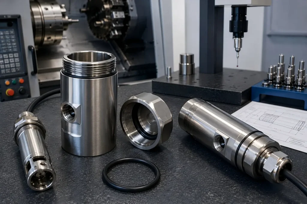
A water quality sensor housing protects electronics, optical elements, electrodes, connectors, and internal wiring from water, chemicals, contamination, and mechanical damage.
CNC machining can produce accurate sealing grooves, bores, threads, end caps, cable-entry features, and sensor interfaces. However, machining accuracy alone does not make a complete sensor assembly waterproof.
Final sealing performance also depends on:
- O-ring selection
- Groove geometry
- Seal compression
- Pressure direction
- Material compatibility
- Surface condition
- Threads and cable entries
- Assembly force
- Seal lubrication
- Cleanliness
- Pressure or immersion testing
- The complete enclosure design
A housing should therefore be reviewed as a sealing system, not only as a machined metal part.
Quick Answer
A reliable CNC-machined water quality sensor housing normally requires:
- A material compatible with the water, chemicals, temperature, and service life
- A clearly defined axial or radial sealing arrangement
- O-ring groove dimensions based on the selected seal and operating conditions
- Controlled sealing surfaces without harmful scratches, burrs, or interrupted contact
- Suitable datums for concentric bores, threads, caps, and sensor features
- Defined dimensions before and after surface treatment
- Inspection of grooves, threads, bores, and mating surfaces
- Assembly procedures that avoid twisting, cutting, or contaminating the seal
- A separate leak, pressure, immersion, or ingress-protection test plan
CMM inspection can verify dimensions and geometric relationships. A profilometer can verify specified surface roughness. Neither measurement alone proves that the complete sensor assembly meets an IP rating or a required operating pressure.
What CNC Machining Can and Cannot Guarantee
CNC machining can help control:
- O-ring groove diameter, width, and depth
- Bore diameter and roundness
- End-cap fit
- Thread size and position
- Mating-face flatness
- Concentricity between sealing and assembly features
- Sensor-window or electrode position
- Cable-entry geometry
- Surface roughness where specified
- Burr and edge condition
CNC machining cannot independently guarantee:
- Waterproof performance of the complete assembly
- O-ring chemical compatibility
- Correct seal compression under every temperature
- Long-term immersion performance
- Cable-gland sealing
- Connector sealing
- Adhesive or potting reliability
- IP68 or another ingress-protection rating
- Pressure-vessel safety
- Field performance after repeated assembly
The drawing, seal specification, assembly process, and validation plan must work together.
Main Leakage Paths in a Sensor Housing
Water does not only enter through the main end cap.
A sensor housing may contain several potential leakage paths.
End-Cap Seal
The primary O-ring may be placed between:
- A removable cap and cylindrical body
- Two bolted flange faces
- A threaded cap and shoulder
- A cartridge and outer enclosure
Incorrect groove geometry, damaged edges, seal twist, poor compression, or surface scratches can create a leakage path.
Cable Entry or Electrical Feedthrough
The machined body may seal correctly while water enters through:
- A cable gland
- Connector threads
- A potted cable
- A welded feedthrough
- An overmolded cable interface
- A damaged strain relief
Cable-entry validation should be included in the complete enclosure test.
Sensor Window or Electrode Interface
Optical windows, membranes, electrodes, and sensing tips may use:
- O-rings
- Gaskets
- Adhesives
- Retaining threads
- Compression rings
- Welded or bonded joints
These interfaces need their own dimensional and sealing review.
Threaded Joints
Threads are not automatically watertight.
The design may require:
- An O-ring below the thread
- A bonded sealing washer
- A thread sealant
- A tapered pipe thread
- A gasketed shoulder
- A welded or permanently bonded joint
The drawing should make the sealing method clear.
Scratches and Burrs
A dimensionally correct groove may still fail if it contains:
- Rolled burrs
- Sharp edges
- Spiral tool marks
- Deep scratches
- Embedded chips
- Handling damage
- Coating buildup
- Contamination
Seal contact areas require both dimensional and visual control.
Axial vs Radial O-Ring Seals
The first design decision is whether the seal is compressed axially or radially.
Axial Face Seal
An axial seal is compressed between two opposing faces.
Typical examples include:
- Flange covers
- Flat end caps
- Bolted lids
- Sensor windows
- Connector plates
The groove may be located in either mating face.
Pressure direction matters. For an internal-pressure face seal, the O-ring should be supported so pressure helps energize it without pushing it out of the groove. External-pressure or vacuum arrangements may require a different groove reference.
Radial Seal
A radial seal is compressed between cylindrical surfaces.
Typical arrangements include:
- A plug inserted into a bore
- A cylindrical cap sliding over a housing
- A removable sensor cartridge
- A piston-style end closure
Radial sealing performance depends on more than groove depth. It also depends on:
- Bore or plug diameter
- O-ring cross-section
- Diametral clearance
- Extrusion gap
- Pressure
- Temperature
- Assembly movement
- Surface finish
- Lead-in geometry
Parker’s O-ring design guidance separates face-seal and radial-seal glands and uses different groove, clearance, finish, pressure-direction, and size relationships. This is why one universal groove-depth tolerance cannot be applied to every sensor housing.
O-Ring Information Required Before Machining
An O-ring groove should not be machined from a groove depth alone.
The supplier should receive or confirm:
| Required Information | Why It Matters |
|---|---|
| O-ring standard and size | Controls cross-section and installed geometry |
| Elastomer material | Affects chemical, temperature, and compression behavior |
| Shore hardness | Influences deformation and extrusion resistance |
| Axial or radial seal | Determines the gland arrangement |
| Static or dynamic use | Changes surface and wear requirements |
| Internal or external pressure | Affects seal direction and groove reference |
| Operating pressure | Influences extrusion-gap and backup-ring decisions |
| Vacuum requirement | May require different surface and sealing controls |
| Temperature range | Changes seal dimensions and material behavior |
| Water or chemical medium | Determines elastomer compatibility |
| Assembly frequency | Affects lead-in, lubrication, and damage risk |
| Surface-treatment condition | Coating may change groove and mating dimensions |
| Required test | Defines how the finished enclosure will be verified |
The drawing should identify whether groove dimensions apply:
- Before passivation
- Before anodizing
- After coating
- In the assembled condition
- With or without masking
Do not add a tighter groove tolerance only because the application is described as “underwater.” The tolerance must relate to the selected seal design and the actual functional risk.
Material Selection for Water Quality Sensor Housings
There is no single best housing material for every sensor.
The decision depends on:
- Freshwater, seawater, wastewater, or chemical exposure
- Chloride level
- pH
- Temperature
- Biofouling
- Electrical isolation
- Weight
- Strength
- Impact risk
- Required service life
- Cleaning chemicals
- Surface-treatment requirements
- Cost and quantity
316L Stainless Steel
316L is a common starting point for water-monitoring and industrial sensor housings because it provides:
- Good general corrosion resistance
- Useful strength
- Stable threads and sealing features
- Compatibility with passivation
- Broad availability
However, 316L is not universally immune to corrosion.
Chlorides, stagnant crevices, high temperature, low oxygen, aggressive cleaning chemicals, and long-term seawater exposure can increase pitting or crevice-corrosion risk. Nickel Institute guidance notes that 316L offers greater chloride resistance than 304, while more highly alloyed stainless or nickel alloys may be required for more severe service.
The buyer should define the actual medium rather than writing only:
For underwater use.
Titanium
Titanium may be considered when the project requires:
- Low weight
- High specific strength
- Strong seawater-corrosion performance
- Long-term immersion
- Reduced magnetic influence
Its higher material and machining cost should be evaluated against the actual service requirement.
Material grade must be specified. Commercially pure titanium and Ti-6Al-4V do not have identical mechanical, corrosion, machining, or cost characteristics.
Aluminum
Aluminum can be suitable for:
- Portable freshwater instruments
- Shorter-life monitoring equipment
- Lightweight housings
- Protected industrial environments
- Cost-sensitive prototypes
The anodizing specification, coating damage risk, galvanic contact, threaded interfaces, and exposed machined areas require review.
Hard anodizing does not turn aluminum into a universally corrosion-proof material. Masking, coating thickness, electrical-contact areas, and post-finish dimensions must be defined.
PEEK and Engineering Plastics
PEEK or another engineering plastic may be considered when the project needs:
- Electrical insulation
- Low weight
- Nonmetallic construction
- Selected chemical resistance
- Reduced galvanic interaction
Plastic housings also introduce different risks:
- Thread creep
- Seal-groove deformation
- Moisture absorption in some materials
- Lower stiffness
- Temperature-dependent dimensions
- Stress concentration
- Assembly-force limits
Chemical compatibility must be checked against the exact polymer grade and water-treatment chemicals.
For broader grade and stock-form planning, review our CNC machining materials guide.
Datum Planning for Cylindrical Sensor Housings
Many sensor housings combine turning and milling features.
A typical part may include:
- A cylindrical outer body
- A deep internal bore
- Internal or external threads
- One or more O-ring grooves
- A sensor opening
- Cross holes
- Flats or wrench features
- A connector or cable port
- Mounting holes
The datum system should reflect assembly function.
For example:
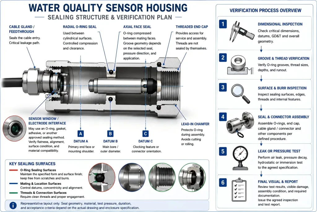
- Datum A: Primary end face or mounting shoulder
- Datum B: Main cylindrical bore or outer diameter
- Datum C: Clocking flat, cross hole, or connector feature
The most important relationships may include:
- Seal groove to mating bore
- End face to thread axis
- Sensor opening to central axis
- Connector port to clocking feature
- Window seat to housing shoulder
- Mounting interface to sensing tip
Do not apply a blanket ±0.01 mm tolerance to every feature. Use dimensional tolerances and GD&T where they protect sealing, alignment, assembly, or sensor performance.
For datum, fit, flatness, position, and inspection planning, see our CNC machining tolerances guide.
Deep Bores and Internal Features
Long sensor bodies often contain deep internal bores.
Potential machining risks include:
- Boring-bar deflection
- Bore taper
- Poor chip evacuation
- Chip recutting
- Internal tool marks
- Incomplete deburring
- Inspection access
- Coolant trapped inside the part
A machining plan may use:
- Drilling followed by boring
- Reaming for suitable straight bores
- Multiple boring tools
- Through-tool coolant where appropriate
- Controlled chip evacuation
- Separate finishing passes
- In-process bore measurement
- Dedicated cleaning after machining
The inspection method should match the depth and tolerance. A caliper cannot verify every deep-bore feature.
Threads, Lead-Ins, and Assembly Protection
Threaded caps and connectors should be reviewed for:
- Thread standard
- Class or fit
- Engagement length
- Runout
- Relief grooves
- Seal position
- Coating allowance
- Galling risk
- Tool access
- Deburring
- Assembly torque
A sharp entry can cut an O-ring during assembly.
Depending on the seal and design, the part may need:
- A controlled lead-in chamfer
- Rounded or broken edges
- Burr-free thread starts
- A protected groove edge
- Clean assembly surfaces
The edge condition should follow the seal design rather than a generic deburr all edges note.
Surface Finish for Sealing Areas
Ra 0.8 μm should not automatically be described as a mirror finish.
Surface roughness is only one part of seal-interface quality.
Two surfaces with the same measured Ra may have different:
- Tool-mark direction
- Waviness
- Scratches
- Chatter
- Spiral lead
- Local pits
- Edge damage
- Reflectivity
A static O-ring face, radial sliding surface, gasket face, adhesive seat, and optical-window interface may require different controls.
The drawing may need to define:
- Roughness value
- Measurement direction
- Lay direction
- Waviness or form requirement
- Cosmetic zone
- Prohibited scratches
- Coating condition
- Whether the value applies before or after finishing
For anodizing, passivation, masking, polishing, and post-finish inspection, review our surface finishes for CNC parts.
Inspection Before Assembly
Dimensional inspection should focus on the features that control sealing and assembly.
O-Ring Groove Inspection
Depending on groove design, inspect:
- Groove diameter
- Groove width
- Groove depth
- Concentricity
- Runout
- Bottom condition
- Corner radii
- Entry-edge condition
- Surface finish
- Coating buildup
Bore and Cap Inspection
Possible checks include:
- Bore diameter
- Plug diameter
- Roundness
- Cylindricity
- Straightness
- Axial position
- Shoulder depth
- Mating clearance
Thread Inspection
Thread verification may use:
- GO/NO-GO thread gauges
- Ring gauges
- Plug gauges
- Optical inspection
- Defined thread-depth checks
- Mating-part assembly tests
Visual and Cleanliness Inspection
Before assembly, verify:
- No chips inside the cavity
- No burrs near wires or seals
- No scratches across the seal path
- No damaged coating
- No embedded blasting media
- No handling dents
- No contamination on O-rings or mating faces
Rapid Efficient’s quality assurance for CNC machined parts explains how dimensional, thread, surface, burr, appearance, and reporting requirements can be planned according to the drawing.
Dimensional Inspection Is Not a Leak Test
A housing may pass every dimensional check and still leak because of:
- The wrong O-ring material
- Damaged seals
- Incorrect assembly
- Cable-gland failure
- Connector leakage
- Surface scratches
- Poor lubrication
- Thermal movement
- Pressure cycling
- Chemical attack
- Potting or bonding defects
Dimensional inspection verifies the manufactured geometry.
Leak or pressure testing verifies the assembled sealing system under defined conditions.
Both may be necessary.
Leak, Pressure, Immersion, and IP Test Planning
The buyer should specify what must be proven.
Air Leak or Pressure-Decay Test
This may be used to detect leakage from an assembled housing under a defined gas pressure and test duration.
The plan should define:
- Test medium
- Pressure
- Stabilization time
- Test time
- Allowable pressure loss or leak rate
- Temperature
- Fixture volume
- Calibration method
Bubble Test
A pressurized assembly may be immersed while the operator checks for visible bubbles.
This is simple but depends on:
- Pressure
- Observation time
- Leak location
- Bubble size
- Operator judgment
Hydrostatic Pressure Test
A water-filled or externally pressurized test may be used where the product must withstand submersion or hydrostatic pressure.
The specification should distinguish:
- Proof pressure
- Operating pressure
- Test duration
- External or internal pressure
- Functional acceptance
- Permanent-deformation limit
- Leakage acceptance
Immersion Test
A basic immersion check may confirm water ingress under a defined depth and time.
It does not automatically represent:
- Long-term field deployment
- Repeated pressure cycles
- Ocean depth
- Chemical exposure
- Temperature cycling
- High-pressure washdown
IP Testing
IEC 60529 defines a system for classifying the protection provided by electrical-equipment enclosures against access, solid objects, and water ingress. Compliance is established through the applicable enclosure test—not by machining tolerances alone.
Therefore, an engineering drawing, CMM report, or roughness report can support the enclosure design, but it cannot by itself certify a complete assembly as IP68, IP69, or another rating.
The required standard, configuration, test condition, sample quantity, and acceptance criteria should be agreed before quotation.
Prototype Testing Before Repeat Production
A sensible validation route may include:
- Material and drawing review
- First CNC-machined housing
- Dimensional inspection
- Surface treatment
- Seal and component assembly
- Leak or pressure test
- Disassembly and damage review
- Design or process correction
- First-article approval
- Repeat production
After testing, inspect:
- O-ring cuts
- Flattening or extrusion
- Surface scratches
- Thread damage
- Coating damage
- Permanent housing deformation
- Water inside the electronics cavity
- Cable-entry movement
- Connector leakage
A passed prototype does not remove the need for production controls. Batch testing frequency should follow project risk and customer requirements.
Questions to Confirm Before Quotation
Provide the following information when requesting a CNC sensor housing quote:
- 3D CAD model
- 2D drawing
- Sensor application
- Freshwater, seawater, wastewater, or chemical medium
- Material grade
- Required surface treatment
- Operating temperature
- Operating pressure or immersion depth
- Proof-test requirement
- Required IP or enclosure standard
- O-ring size and material
- Axial or radial seal arrangement
- Cable-gland or connector details
- Critical dimensions and GD&T
- Dimensions that apply after finishing
- Cosmetic requirements
- Quantity
- Material certificate requirements
- Inspection-report requirements
- Leak or pressure-test responsibility
Do not convert an immersion depth directly into a machining tolerance. The housing geometry, seal design, assembly, material, and test method must be reviewed together.
FAQ
Can CNC Machining Guarantee a Waterproof Sensor Housing?
No manufacturing process can guarantee waterproof performance from machining dimensions alone.
CNC machining can produce controlled grooves, bores, threads, and mating surfaces. The complete assembly must still be validated with the specified seals, connectors, cables, surface treatment, assembly process, and leak or ingress test.
What Is the Best Material for a Water Quality Sensor Housing?
There is no universal best material.
316L may suit many freshwater and industrial applications. Titanium may be considered for demanding marine or low-weight projects. Aluminum may suit lighter and less aggressive environments. PEEK may be useful where electrical isolation or nonmetallic construction is required.
The actual medium and service conditions must control the choice.
What Tolerance Is Required for an O-Ring Groove?
It depends on:
- O-ring size
- Seal type
- Groove arrangement
- Pressure
- Temperature
- Elastomer
- Clearance
- Surface treatment
- Assembly method
A universal +0.01/-0.00 mm groove-depth tolerance should not be applied without reviewing the complete seal design.
Does Every Sealing Surface Need Ra 0.8 μm?
No.
The required roughness and surface pattern depend on the seal type, pressure, motion, material, and supplier recommendation. A lower Ra number is not automatically better if the surface has harmful waviness, spiral marks, scratches, or an unsuitable lay direction.
Is IP68 the Same as a 20-Bar Pressure Rating?
No.
An IP designation and a pressure rating answer different validation questions. The applicable standard, depth or pressure, duration, enclosure configuration, and acceptance criteria must be specified.
Should Stainless Sensor Housings Be Passivated?
Passivation may be specified for stainless-steel parts to support surface cleanliness and corrosion performance after machining.
The required standard, cleaning route, masking, documentation, and post-treatment inspection should be included in the purchase requirements.
Should Aluminum Sensor Housings Be Hard Anodized?
Hard anodizing may be useful for selected wear or surface-protection requirements, but it can change dimensions and affect threads, grooves, bores, electrical contact, and appearance.
The coating requirement and masking plan must be reviewed before machining.
Who Should Perform the Leak Test?
The machining supplier, assembly supplier, test laboratory, or customer may perform it.
Responsibility should be agreed before quotation together with the test method, pressure, medium, duration, sample quantity, fixture, report format, and acceptance criteria.
Review Your Sensor Housing Before Machining
Send the complete drawing package together with the operating environment, sealing arrangement, material, pressure or immersion requirement, surface treatment, connector information, inspection requirements, and planned validation method.
Rapid Efficient can review:
- Machining access
- Datum structure
- O-ring grooves
- Threads and lead-ins
- Deep bores
- Material selection
- Surface-treatment allowance
- Critical inspection points
- Prototype and low-volume manufacturing requirements
- Packaging and international delivery needs
For cylindrical bodies, caps, threaded interfaces, and concentric sealing features, review our precision machining services.