Concentricity is commonly used to describe how closely two or more circular or cylindrical features share the same center or axis.
Typical examples include:
- A shaft and its bearing journals
- Front and rear bearing bores in a motor housing
- Multiple diameters on a turned component
- A bore and an outside diameter
- A spindle and its mounting surfaces
- Sealing diameters in a pump component
- Gear, pulley, and coupling interfaces
However, the word concentricity can mean different things in everyday engineering discussion, legacy GD&T drawings, inspection reports, and supplier communication.
A drawing that simply says “keep these features concentric” is incomplete unless it also defines:
- The datum
- The controlled feature
- The applicable drawing standard
- The tolerance type
- The tolerance value
- The inspection method
- The condition in which the part will be inspected
Quick Answer
In practical CNC machining, concentricity usually means that important circular features should remain centered around a common functional axis.
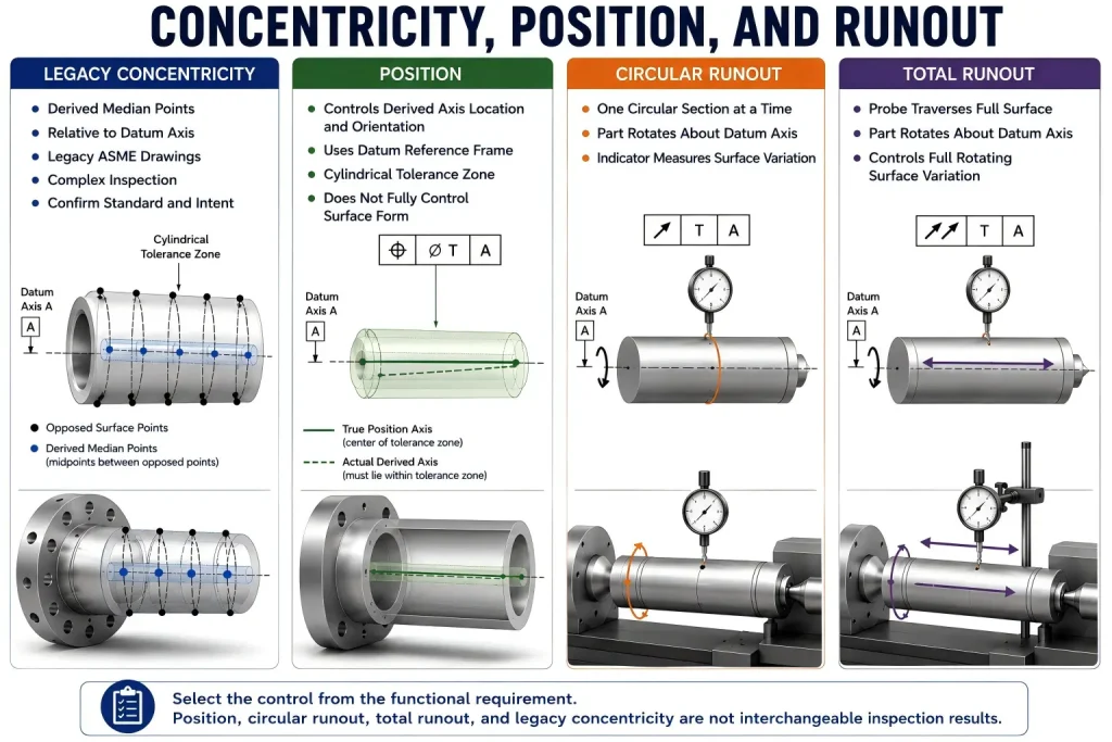
But under older ASME GD&T practice, concentricity had a more specific meaning: it controlled the derived median points of a feature relative to a datum axis.
The concentricity symbol was removed from ASME Y14.5-2018. New drawings commonly use:
- Position when the derived axis of a hole, shaft, or other feature of size must be located relative to datums.
- Circular runout when surface variation at individual circular sections matters during rotation.
- Total runout when the full rotating surface must be controlled along its length.
- Profile or other controls when the functional requirement involves a more complex surface relationship.
Legacy drawings may still contain a concentricity callout. Do not silently reinterpret it. Confirm the drawing standard, design intent, datum axis, inspection method, and acceptance rule before quotation or production.
Concentricity in Plain Engineering Language
In ordinary shop and design discussions, engineers may use concentricity to describe features such as:
- Two bores that should share one axis
- A turned outside diameter centered on an internal bore
- Several shaft journals aligned with each other
- A gear mounting diameter aligned with a bearing journal
- A housing bore centered relative to a pilot diameter
This language communicates the general functional goal, but it does not define a complete GD&T requirement.
For example, the phrase:
The front and rear bearing bores must be concentric.
does not tell the manufacturer:
- Which bore establishes the datum axis
- Whether the requirement applies to the feature axis or the actual surface
- Whether form error is included
- Whether the part should be rotated during inspection
- Whether the tolerance zone is diametrical
- Whether the bores are inspected in the clamped or released condition
A controlled drawing should translate the functional goal into a measurable requirement.
The Legacy ASME Meaning of Concentricity
On legacy ASME drawings, concentricity did not simply compare two fitted cylinder axes.
The control related the derived median points of diametrically opposed surface elements to a cylindrical tolerance zone centered on the datum axis.
This made true concentricity difficult to inspect because the measurement process had to evaluate multiple opposed surface points through multiple cross-sections.
It was not equivalent to:
- Checking one diameter with a dial indicator
- Comparing two fitted circle centers
- Measuring one axis from a small number of CMM points
- Checking only the maximum and minimum bore diameter
- Measuring total indicated runout
For that reason, designers reviewing legacy drawings should first determine what functional problem the original callout was intended to prevent.
Concentricity, Coaxiality, Position, and Runout
These terms are related, but they are not interchangeable.
| Term | What it generally controls or describes | Typical use |
|---|---|---|
| Concentricity | On legacy ASME drawings, the derived median points of a feature relative to a datum axis | Legacy drawings or special mass-distribution requirements |
| Coaxiality | A functional description that multiple cylindrical features share one axis | Engineering communication; requires a defined drawing control |
| Position | The location and orientation of a derived axis relative to datums and basic dimensions | Bearing bores, shaft features, hole patterns, fitted interfaces |
| Circular runout | Surface variation at one circular section while the part rotates around a datum axis | Journals, sealing diameters, bearing surfaces |
| Total runout | Surface variation over the full controlled surface while the part rotates and the indicator traverses its length | Long journals, spindle surfaces, precision rotating diameters |
| Cylindricity | The form of a cylindrical surface without reference to a datum | Controlling roundness, straightness, and overall cylinder form |
| Circularity | The form of each individual circular section without reference to a datum | Roundness of bores, journals, and turned diameters |
The correct control depends on what the assembly actually needs.
Position vs Concentricity
Position is often a more practical choice when the functional requirement is:
Keep the axis of this bore or shaft correctly located relative to the datum system.
Position may be appropriate for:
- Front and rear bearing bores
- A shaft diameter located from a datum journal
- A precision bore located from mounting datums
- A hole or cylindrical feature related to an assembly coordinate system
- Multiple features whose axes must align with a functional datum structure
Position controls a derived axis rather than the complete rotating surface.
A feature can meet its position requirement and still have:
- Roundness error
- Taper
- Barrel shape
- Surface waviness
- Local damage
- Excessive runout
The drawing may therefore need separate size, form, or runout controls when those conditions affect function.
For broader tolerance planning, review our CNC machining tolerances guide.
Circular Runout vs Concentricity
Circular runout evaluates surface variation at an individual circular section while the part rotates around a datum axis.
It is commonly checked with an indicator or suitable form-measurement equipment.
Circular runout can respond to combined effects such as:
- Centering error at the measured section
- Local roundness error
- Surface irregularity
- Orientation error relative to the datum axis
It is often more closely connected to actual rotating contact than legacy concentricity.
Possible applications include:
- Bearing journals
- Seal diameters
- Pulley mounting surfaces
- Shaft shoulders
- Precision pilots
- Gear mounting diameters
A dial-indicator runout reading should not automatically be reported as legacy GD&T concentricity. They are different controls and use different evaluation methods.
Total Runout vs Concentricity
Total runout evaluates variation across the full controlled rotating surface while the measuring probe moves along that surface.
It may respond to combined effects including:
- Axis misalignment
- Circularity error
- Surface straightness error
- Taper
- Barrel or hourglass shape
- Local surface variation
- Orientation relative to the datum axis
Total runout can be useful for:
- Long bearing journals
- Spindle surfaces
- Precision shaft diameters
- Roller surfaces
- Rotating seal interfaces
- Multiple functional regions along one diameter
It is generally a stronger surface control than checking only one circular section.
Coaxiality Is a Functional Goal, Not a Complete Drawing Instruction
Engineers often use coaxiality to describe two or more cylindrical features that should share one axis.
That description is useful, but the drawing still needs to state how the requirement will be controlled.
Depending on the function, the designer may choose:
- Position
- Circular runout
- Total runout
- A combination of size, position, and form controls
- A customer-specific requirement under another applicable standard
- A functional assembly or gauging method
Writing only:
Coaxial within 0.01 mm
can create disagreement because it does not clarify:
- Diameter or radial deviation
- Axis fitting method
- Surface sampling
- Datum establishment
- Feature length
- Inspection equipment
- Whether form error is included
How to Choose the Correct Control
Use the part function rather than the terminology alone.
| Functional requirement | Control to review |
|---|---|
| Locate a bore axis relative to mounting datums | Position |
| Locate one shaft diameter relative to a datum journal | Position or runout, depending on function |
| Limit surface variation at one rotating section | Circular runout |
| Limit variation over an entire rotating surface | Total runout |
| Control cylinder form without a datum | Cylindricity |
| Control individual circular-section form | Circularity |
| Protect an equal-mass or legacy derived-median-point requirement | Review the legacy concentricity definition |
| Verify actual assembly rotation | Runout or a functional test may be more relevant |
| Align several separated bores | Position, runout, or a project-specific coaxial inspection plan |
The design team, manufacturer, and inspection team should agree on the same interpretation before production begins.
Why Shared-Axis Accuracy Matters
Poor alignment between rotating or mating features may contribute to:
- Bearing preload variation
- Uneven bearing loading
- Shaft wobble
- Vibration
- Noise
- Seal wear
- Leakage
- Uneven gear contact
- Coupling misalignment
- Increased friction
- Shortened component life
- Assembly difficulty
The severity depends on:
- Rotational speed
- Load
- Bearing arrangement
- Shaft length
- Feature diameter
- Clearance
- Seal design
- Material stiffness
- Lubrication
- Operating temperature
- Assembly method
A slow manual mechanism and a high-speed spindle should not automatically receive the same axis-control requirement.
Common CNC Parts With Shared-Axis Requirements
Motor Housings
Front and rear bearing bores may need a controlled relationship to reduce bearing misalignment and rotor interference.
Shafts
Bearing journals, seal diameters, threads, shoulders, and coupling features may need to remain related to the functional datum axis.
Gear and Pulley Components
The gear teeth or belt surface may need to rotate consistently relative to the bore or mounting pilot.
Pump and Valve Components
Bores, sealing diameters, shaft passages, and rotating interfaces may require controlled alignment.
Precision Bushings
The inside diameter and outside diameter may need a stable relationship for assembly and wall-thickness control.
Spindles
Long rotating surfaces may require size, form, runout, surface finish, and thermal-stability requirements rather than one general “concentricity” note.
Bearing Carriers and Gear Housings
Separated bores may need alignment relative to a common datum structure and assembly interface.
There Is No Universal “Good Concentricity” Value
A fixed table such as:
- General part: 0.05 mm
- Precision part: 0.02 mm
- High-speed part: 0.01 mm
- Ultra-precision part: 0.005 mm
should not be used as a universal design rule.
The appropriate requirement depends on:
- Feature diameter
- Feature length
- Rotational speed
- Bearing clearance
- Load
- Seal design
- Noise target
- Assembly stack-up
- Datum quality
- Material
- Wall thickness
- Surface finish
- Heat treatment
- Coating
- Inspection method
- Measurement uncertainty
- Production quantity
A tolerance value also needs the correct context.
For example:
- A position tolerance may define a diametrical cylindrical zone.
- An indicator may report total indicated runout.
- A CMM may report radial or diametrical deviation depending on the program.
- A customer report may use axis offset or maximum center displacement.
These numbers should not be compared until the definitions are aligned.
How CNC Machining Controls Shared Axes
1. Start With the Functional Datum
The most important axis is not always the easiest surface to clamp.
The datum should represent the functional relationship of the assembly.
Possible datum features include:
- A bearing journal
- A precision bore
- A mounting pilot
- A fitted outside diameter
- A face-and-bore combination
- A qualified set of mounting surfaces
Poor datum selection can create a part that measures correctly in the machining setup but fails in the real assembly.
For a deeper explanation of primary, secondary, and tertiary references, review types of CNC machining datums.
2. Machine Related Features in One Qualified Setup
Machining critical diameters or bores without removing the part can reduce datum-transfer error.
Examples include:
- Turning several shaft journals in one chucking
- Boring front and rear features from one accessible direction
- Finishing an outside diameter and an internal bore in one setup
- Machining a pilot and bearing seat from the same datum structure
One setup does not automatically guarantee good alignment.
The result still depends on:
- Machine spindle condition
- Tool runout
- Chuck or collet condition
- Fixture rigidity
- Cutting force
- Thermal behavior
- Tool deflection
- Part geometry
- Material movement
3. Control Chuck, Collet, and Soft-Jaw Runout
A turned part may inherit error from:
- Worn chuck jaws
- Damaged collets
- Dirty contact surfaces
- Incorrect soft-jaw boring
- Excessive jaw pressure
- Poor part seating
- Short gripping length
- Part deformation
- Re-clamping on an unqualified surface
For critical turned features, the setup may require:
- Bored soft jaws
- A qualified collet
- Controlled gripping length
- Defined clamping pressure
- An indicator check after loading
- A sacrificial machining feature
- A final setup from the functional datum
For more turning-specific considerations, review CNC turning parts.
4. Plan the Boring and Finishing Sequence
Bore alignment can be affected by:
- Boring-bar overhang
- Tool deflection
- Interrupted cuts
- Deep-hole access
- Chip evacuation
- Uneven stock
- Tool wear
- Heat
- Thin walls
- Inconsistent finishing allowance
Possible process decisions include:
- Rough boring followed by finish boring
- Controlled stock allowance
- Shorter and more rigid boring tools
- Finish passes from the functional datum
- Tool-wear monitoring
- In-process measurement
- A dedicated finishing setup
- Reinspection after the part stabilizes
The correct route depends on the bore length, diameter, material, geometry, and drawing requirement.
5. Protect the Datum During Setup Transfer
Some parts cannot be completed in one setup.
When the part is re-clamped, the second setup should locate from qualified features that preserve the required functional relationship.
Setup-transfer risks include:
- Chips on locating surfaces
- Burrs
- Locator wear
- Incorrect work offsets
- Fixture movement
- Part tilt
- Inconsistent clamp sequence
- Datum features that are too short or unstable
- Using a rough surface as a final reference
- Reversing the part from a nonfunctional diameter
The setup plan should state:
- Which feature establishes the new axis
- Which face controls axial position
- How rotation is constrained
- How the work offset is established
- How the setup is checked before finishing
- Which features will be inspected after transfer
6. Control Thin-Wall Distortion
Thin-wall housings can appear aligned while clamped and move after release.
Excessive clamping force may cause:
- Bore ovality
- Axis shift
- Taper
- Local deformation
- Face distortion
- Runout after unclamping
The process may require:
- Larger contact areas
- Lower controlled clamping force
- Purpose-built fixtures
- Balanced material removal
- Roughing and finishing stages
- Rest or stabilization time
- Inspection in the released condition
- A defined restrained condition when function requires it
The drawing and inspection plan should clarify whether acceptance applies in the free state or in an agreed restrained condition.
7. Manage Material Movement
Removing large amounts of material can release residual stress.
The risk is higher for:
- Thin-wall housings
- Long shafts
- Heavily pocketed parts
- Asymmetrical components
- Welded blanks
- Heat-treated material
- Parts with uneven stock
- Components with interrupted sections
A suitable process may include:
- Reviewing the stock form and material condition
- Balanced roughing
- Controlled finishing allowance
- Multiple machining stages
- Requalification of datums
- Stabilization before final inspection
- Post-treatment inspection when required
8. Control Tool and Machine Conditions
Shared-axis features may be affected by:
- Spindle condition
- Toolholder runout
- Boring-tool deflection
- Tailstock alignment
- Live-center condition
- Turret alignment
- Machine warm-up
- Temperature change
- Probe calibration
- Tool wear
- Unstable cutting conditions
Machine capability should be evaluated together with the complete setup and measurement process.
A high-spec machine cannot compensate for an unstable datum, distorted part, damaged fixture, or incorrect inspection alignment.
9. Review Surface Treatment and Heat Treatment
Anodizing, plating, coating, heat treatment, and stress relief may affect:
- Feature size
- Fits
- Surface condition
- Distortion
- Final runout
- Measurement repeatability
Critical requirements should clarify whether they apply:
- Before finishing
- After finishing
- On a masked surface
- After heat treatment
- After grinding
- In the final delivered condition
Post-process inspection may be necessary for bearing seats, seal diameters, precision bores, journals, and other rotating interfaces.
How Is Concentricity or Coaxial Alignment Measured?
The inspection method must match the drawing requirement.
No single instrument is best for every feature.
Dial Indicator
A dial indicator is commonly used to evaluate runout while a part rotates around an established datum axis.
It is useful for:
- Shaft journals
- Pilots
- Seal surfaces
- Bearing diameters
- Face runout
- Setup verification
- Quick production checks
A dial indicator directly measures surface movement at the contact point.
It does not automatically evaluate legacy derived-median-point concentricity.
The result can also be affected by:
- Datum setup
- Fixture runout
- Center condition
- Surface roughness
- Probe position
- Part rotation
- Dirt or burrs
- Operator technique
Coordinate Measuring Machine
A CMM can measure features and relate them to a datum-based part coordinate system.
Depending on the drawing and measurement plan, it may evaluate:
- Feature position
- Bore or shaft axes
- Datum relationships
- Multiple separated bores
- Profiles
- Perpendicularity
- Selected runout requirements
- Legacy requirements when an appropriate evaluation method is defined
CMM results depend on:
- Datum alignment
- Number and distribution of measured points
- Feature length
- Probe access
- Fitting algorithm
- Filtering
- Part temperature
- Fixture condition
- Measurement uncertainty
- Software evaluation method
A CMM report should identify what characteristic was actually evaluated.
For a detailed inspection-planning guide, review CMM inspection for CNC-machined parts.
Roundness and Cylindricity Measuring Equipment
A form-measurement machine can be useful for detailed evaluation of rotating geometry.
Depending on the equipment and setup, it may assess:
- Circularity
- Cylindricity
- Coaxial relationships
- Circular runout
- Total runout
- Taper
- Surface form along a rotating feature
This approach can provide more detailed rotational form data than a simple single-point indicator check.
The datum setup, centering, leveling, probe path, filtering, and evaluation standard must still be controlled.
Bore Gauge
A bore gauge is useful for checking:
- Bore diameter
- Taper
- Bellmouth
- Barrel shape
- Ovality at selected sections
- Size variation along the bore
A bore gauge alone normally does not prove that two separated bores share the same datum axis.
It should be combined with another alignment, fixture, CMM, runout, or functional inspection method when axis relationship matters.
Functional Gauge or Assembly Test
A functional gauge may be useful when the real requirement is:
- A shaft must pass through two aligned bores
- Bearings must assemble without binding
- A pilot must fit a mating component
- A seal must run without excessive motion
- A gear or pulley must rotate within an agreed limit
Functional checks can be valuable, but they should not silently replace the drawing requirement.
The gauge design, wear limits, acceptance method, and correlation with dimensional inspection should be agreed in advance.
Inspection-Method Comparison
| Inspection method | Useful for | Does not automatically prove |
|---|---|---|
| Dial indicator | Circular or face runout, setup checks, rotating surface variation | Legacy derived-median-point concentricity |
| CMM | Datum-related axes, position, multi-feature relationships, documented reports | Reliable results without correct alignment, sampling, and evaluation |
| Roundness machine | Circularity, cylindricity, rotational form, detailed runout evaluation | Assembly function without the correct datum and setup |
| Bore gauge | Bore size, taper, ovality, local size variation | Shared axis between separated bores |
| Micrometer | Shaft diameter and local size | Axis alignment or runout |
| Functional gauge | Assembly-related pass/fail behavior | The cause of failure or every individual GD&T characteristic |
Common Drawing Mistakes
Calling Everything Concentricity
Different functions may require position, circular runout, total runout, cylindricity, or a combination of controls.
Missing Datum References
A shared-axis requirement needs a clear reference.
Using a Fixed “Good” Tolerance
The required value should come from function, not a generic tolerance chart.
Confusing Diameter and Radial Values
A diametrical position zone, radial axis offset, and total indicator reading are not automatically equivalent.
Ignoring Feature Length
A short bore and a long bore may produce very different axis-evaluation results.
Applying the Requirement to the Wrong Feature
The drawing may control a nonfunctional outside diameter while the bearing bore actually determines assembly performance.
Ignoring Surface Form
An axis may be well located while the surface still has excessive roundness, taper, or cylindricity error.
Failing to Define Final Condition
Heat treatment, anodizing, plating, grinding, assembly preload, or clamping may change the delivered result.
Common Manufacturing and Inspection Mistakes
- Re-clamping from an unqualified surface
- Using dirty or damaged soft jaws
- Excessive clamping pressure
- Ignoring thin-wall springback
- Finishing one critical bore before heavy roughing elsewhere
- Using excessive boring-bar overhang
- Failing to check tool or spindle runout
- Treating a bore-gauge size result as proof of coaxial alignment
- Reporting dial-indicator runout as GD&T concentricity
- Measuring from the wrong datum
- Using too few CMM points
- Comparing supplier and customer reports with different alignment methods
- Inspecting before finishing when the drawing applies after finishing
- Omitting measurement uncertainty near the tolerance limit
RFQ Checklist for Shared-Axis CNC Parts
Provide the following before quotation:
- 3D CAD model
- Controlled 2D drawing
- Applicable drawing standard and revision
- Material grade
- Temper or hardness condition
- Quantity
- Functional datum features
- Controlled bores and diameters
- Feature lengths
- Position or runout callouts
- Size and fit requirements
- Bearing information
- Mating shafts or housings
- Rotational speed
- Load
- Seal requirements
- Surface-roughness requirements
- Thin-wall areas
- Heat treatment
- Surface finish or coating
- Masking areas
- Inspection method
- Sampling or 100% inspection requirement
- CMM-report requirement
- Functional-gauge requirement
- Final inspection condition
- Packaging requirements
For legacy drawings containing concentricity, also clarify:
- Which ASME or ISO edition applies
- Whether the original design intent is known
- Whether an approved alternative control is allowed
- Whether a customer inspection procedure already exists
- How supplier and customer measurement methods will be correlated
How Rapid Efficient Supports Shared-Axis Features
Rapid Efficient supports custom shafts, housings, bushings, bearing carriers, rotating components, and other CNC-machined metal or engineering-plastic parts.
Project support may include:
- Drawing and DFM review
- Datum-structure review
- Position and runout review
- CNC turning and milling
- Boring-process planning
- Single-setup and multi-setup evaluation
- Workholding review
- Thin-wall risk review
- Surface-finish allowance review
- Dimensional inspection
- CMM reports when requested
- Functional inspection planning
- Material documentation when requested
- Individual protection and international delivery coordination
Final feasibility depends on the material, geometry, feature length, wall thickness, datum structure, tolerance, surface treatment, inspection method, quantity, and measurement requirements.
Learn more about our precision machining services.
After receiving complete drawings, CAD files, quantities, and inspection requirements, Rapid Efficient typically provides quotation feedback within 24 hours.
FAQ
What does concentricity mean in CNC machining?
In everyday machining language, it means that circular or cylindrical features should share a common center or axis. On legacy ASME drawings, concentricity had a specific derived-median-point definition that should not be replaced by a simple runout check without approval.
Is concentricity still used in ASME Y14.5?
The concentricity symbol was removed from ASME Y14.5-2018. It may still appear on legacy drawings created under earlier editions, so the applicable standard and design intent should be confirmed.
What replaced concentricity?
There is no single automatic replacement. Position, circular runout, total runout, profile, or another control may be appropriate depending on the functional requirement.
Is concentricity the same as coaxiality?
Not necessarily. Coaxiality is often used as a general functional description for features sharing an axis. The drawing must still define the actual tolerance, datum, and inspection method.
Is concentricity the same as runout?
No. Legacy concentricity controlled derived median points, while runout evaluates actual surface variation during rotation around a datum axis.
What is the difference between circular runout and total runout?
Circular runout evaluates individual circular sections. Total runout evaluates the controlled surface over its full length as the part rotates.
Can a dial indicator measure concentricity?
A dial indicator is well suited to runout measurement. It does not by itself reproduce the legacy derived-median-point evaluation of concentricity.
Can a CMM measure concentricity?
A CMM can evaluate datum-related feature relationships and may support a defined legacy evaluation. The report must clearly state the alignment, sampling strategy, fitting method, and characteristic being calculated.
Can a bore gauge check coaxiality?
A bore gauge can check diameter, taper, and ovality at selected positions. It generally cannot prove that two separated bores share the same axis without another alignment or inspection method.
What is a good concentricity tolerance?
There is no universal value. The requirement depends on the diameter, feature length, speed, load, bearing system, seal, datum structure, surface form, inspection method, and assembly function.
Why can a thin-wall housing fail after unclamping?
Fixture pressure can deform the housing during machining. When the part is released, the bores may recover unevenly and change size, roundness, alignment, or runout.
Should critical bores be machined in one setup?
Machining related features in one qualified setup can reduce setup-transfer error, but machine condition, tooling, workholding, material movement, and inspection still affect the result.
Request a Drawing and Inspection Review
Send Rapid Efficient your:
- 2D drawing
- 3D model
- Material
- Quantity
- Datum structure
- Controlled bores and shafts
- Position or runout requirements
- Bearing and mating-part information
- Surface treatment
- Inspection expectations
We can review whether the drawing, machining setup, datum-transfer plan, and inspection method clearly protect the required shared-axis relationship.