Quick Answer
RapidEfficient machined a 6061-T6 aluminum optical mount whose manufacturing risk was concentrated in the relationship between its mounting face, hole pattern, locating features and black-anodized final condition. The process was organized around datum control, low-distortion workholding, coordinated machining of related features, finish allowance and feature-specific inspection.
Project Overview
This was an earlier RapidEfficient project for a custom optical mount used in precision instrumentation.
| Project Item | Description |
|---|---|
| Component | CNC-machined optical mount |
| Material | 6061-T6 aluminum |
| Final finish | Matte black anodize |
| Functional priorities | Mounting-face stability, hole-pattern relationships and repeatable mechanical location |
| Manufacturing risks | Datum transfer, clamping distortion, multi-side machining and coating buildup |
| Inspection focus | Mounting face, locating features, fitted interfaces and post-finish condition |
To protect customer confidentiality, identifying information and selected drawing dimensions are not disclosed.
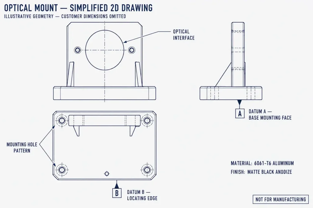
The challenge was not simply producing an aluminum bracket with accurately machined holes. The part had to preserve the mechanical relationships used to locate the optical assembly.
Why an Optical Mount Is More Than a Precision Bracket
An optical mount transfers mechanical variation into the assembled optical system.
However, the relationship is more complex than saying that every dimensional error creates the same amount of optical error. The actual effect depends on the optical layout, lever arm, lens or sensor position, mating components and calibration method.
Our manufacturing responsibility was therefore to control the mechanical interfaces defined on the drawing:
- The primary mounting face
- Locating edges or shoulders
- Hole patterns related to assembly datums
- Fitted bores or locating features
- Threaded mounting points
- Surfaces affected by anodizing
- Cosmetic areas visible after assembly
Flatness alone does not control the orientation of one feature relative to another. A mounting face can meet its flatness requirement while a bore, hole pattern or locating shoulder is still incorrectly oriented.
Likewise, a hole can meet its size limit while its location relative to the mounting datum is incorrect.
The optical axis therefore had to be translated into measurable mechanical features before machining began.
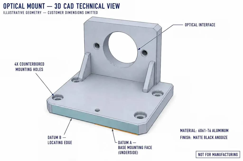
If the mount directly supports a sensitive lens, mirror or other optical element, the drawing should also define the support points, contact geometry and allowable clamping load. These are system-design requirements and should not be inferred from the machined-part geometry alone.
The Main Manufacturing Risks
The project review separated each functional feature from the failure it could create during assembly.
| Feature | Manufacturing Risk | Procurement or Assembly Consequence |
|---|---|---|
| Primary mounting face | Clamping pressure or stock removal changes its free-state form | Rocking, uneven seating or orientation error |
| Datum-related hole pattern | Setup transfer changes the relationship to the mounting face | Difficult assembly or inconsistent component location |
| Fitted bore or locating feature | Size changes after finishing | Loose fit, interference or loss of repeatability |
| Multi-side features | Different setups establish conflicting references | Accumulated positional error |
| Threads and counterbores | Coating buildup or burrs affect engagement | Fastener seating or thread-acceptance problems |
| Matte black finish | Pretreatment exposes tool marks or creates appearance variation | Cosmetic rejection or inconsistent surface condition |
This analysis prevented the process from treating every dimension as equally critical.
The most important characteristics were the relationships controlling assembly. Non-critical exterior dimensions and cosmetic envelopes did not need the same machining and inspection effort.
DFM Review Focused on the Datum Structure
The drawing review started with a simple question:
Which physical surfaces and features locate the optical assembly?
A reliable datum structure should correspond to real, accessible features that can be used during machining, inspection and assembly.
For this type of optical mount, the review should identify:
- The primary mounting surface
- The secondary locating edge or feature
- The feature preventing the remaining degree of movement
- The hole pattern related to those datums
- Any fitted bore, shoulder or optical-interface feature
- Whether the final requirement applies before or after anodizing
A coordinate dimension by itself does not always protect the functional relationship. Where appropriate, position, perpendicularity, parallelism or profile controls may communicate the requirement more clearly.
The correct control depends on the assembly. GD&T should protect function rather than decorate the drawing.
For broader guidance on assigning realistic feature-level requirements, review our CNC machining tolerances guide.
Machining Route for the Optical Mount
We Established the Manufacturing References First
The initial operation created stable machining references before the critical multi-side features were finished.
The manufacturing datum did not have to copy the final design datum blindly. It had to provide stable support, repeatable location and access to the features required in later operations.
The route was planned so that the final functional relationships could still be traced back to the drawing datum structure.
We Avoided Forcing the Part Into a False Shape
Excessive clamping pressure can make a component appear stable during cutting while storing elastic deformation in the part.
After the clamps are released, the component can move toward its free-state shape.
The workholding strategy therefore had to:
- Support rigid areas of the component
- Distribute clamping force
- Avoid loading slender walls or unsupported sections
- Keep chips away from locating surfaces
- Provide repeatable access for subsequent operations
- Allow the part to be checked after release
The objective was not maximum clamping force. It was sufficient restraint without changing the geometry being manufactured.
We Removed the Main Stock Before Final Feature Control
Heavy material removal and final precision finishing were not treated as the same operation.
The main stock was removed before the final mounting and locating relationships were locked. This allowed the component to release most of the movement associated with machining before the final feature-control stage.
Depending on geometry, a suitable route may include:
- Rough machining
- Controlled stock allowance
- Part release
- Re-establishment of the datum system
- Semi-finishing
- Final feature machining
- Free-state inspection
The exact sequence depends on the part geometry, stock form and drawing requirements.
We Kept Related Features Together Where Practical
Every unnecessary setup transfer introduces another opportunity for location error.
Where practical, features sharing a functional relationship were finished without unnecessary datum transfer.
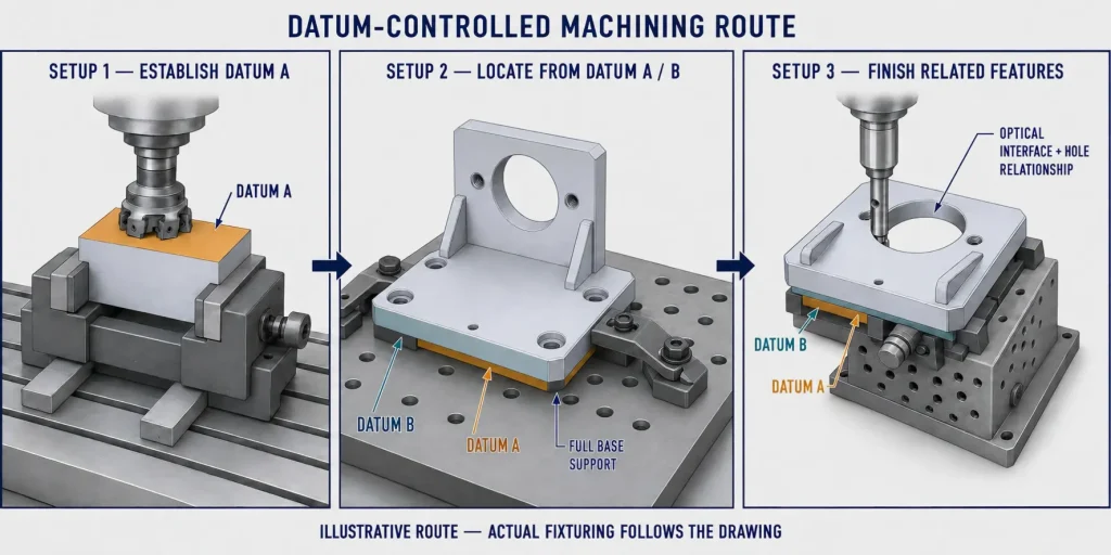
This did not mean that every surface had to be machined in one setup. It meant that the process prioritized the relationships that mattered most.
For example, a mounting face and its related hole pattern may justify coordinated machining or probing. An unrelated cosmetic pocket may not.
We Controlled Burrs Around Assembly Features
Burrs around locating holes, counterbores and threaded features can create false seating even when the measured dimensions appear acceptable.
Deburring therefore had to remove loose or raised material without:
- Enlarging fitted holes
- Rounding functional datum edges
- Damaging thread starts
- Changing counterbore seating surfaces
- Creating inconsistent cosmetic edge breaks
The objective was controlled edge condition, not aggressive polishing.
Preparing the Part for Matte Black Anodizing
Black anodizing was part of the specified final condition, but the coating could not be treated as a purely cosmetic operation.
Anodizing changes the surface of the aluminum and can affect:
- Fitted hole size
- Thread engagement
- Counterbore seating
- Locating shoulders
- Mating faces
- Electrical contact areas
- Cosmetic texture and shade
The drawing therefore needed to clarify which requirements applied:
- Before anodizing
- After anodizing
- On a masked surface
- After thread or fit verification
Masking is not automatically required on every optical mount. It should only be specified where coating buildup would interfere with fit, contact, assembly or another functional requirement.
If a low-glare texture is required, the drawing should define the approved pretreatment and identify functional faces, fitted holes and datum features that must be protected from blasting. A fixed blasting medium or masking route should not be assumed without a released specification.
Matte black appearance also does not define optical reflectance by itself. If stray-light performance is critical, the drawing or specification should state the required optical property, approved finish or acceptance method rather than relying only on the word “black.”
Cleanliness requirements must also be defined where the component will be used near sensitive optics. Particle limits, approved cleaning methods, drying conditions and packaging expectations should come from the project specification rather than being inferred from the anodizing color.
For a wider comparison of coating behavior and drawing requirements, review our aluminum anodizing and powder coating guide.
Inspection Had to Match the Functional Relationship
A single CMM report does not prove every aspect of an optical mount.
The inspection method must match the feature and its function.
| Inspection Feature | What Must Be Verified | Appropriate Inspection Logic |
|---|---|---|
| Primary mounting face | Surface form in the required released or supported state | Evaluate flatness independently of any datum reference |
| Mounting-face orientation | Relationship to another specified feature | Evaluate parallelism or perpendicularity relative to the drawing datum where required |
| Datum-related hole pattern | Location and orientation relative to the drawing datums | CMM alignment to the specified datum reference frame |
| Fitted bore or locating feature | Size, form and assembly condition | Bore gauge, plug gauge, CMM or functional fit check as appropriate |
| Threads | Engagement and coating influence | GO/NO-GO thread gauge after the required finishing stage |
| Counterbores and fastener seats | Diameter, depth and seating condition | Dimensional measurement and visual edge review |
| Anodized appearance | Coverage, texture and agreed cosmetic condition | Visual inspection under defined lighting and viewing conditions |
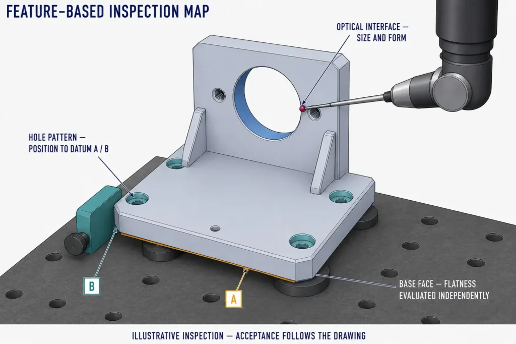
Flatness controls only the form of the selected surface. It does not reference Datum A, B or C.
If the mounting face must remain parallel or perpendicular to another feature, the drawing needs a separate orientation control.
The hole pattern can be evaluated relative to a specified datum reference frame, but the inspection alignment must reproduce the drawing logic rather than use an arbitrary best-fit coordinate system.
Likewise, fitted features need more than a reported center coordinate. Size, form, coating state and functional fit can all affect assembly.
Where documented production evidence is required, the drawing and purchase order should define the expected dimensional report, sampling plan and first article inspection requirements before machining begins.
Project Outcome
RapidEfficient completed the optical-mount project using a machining route built around datum relationships, controlled workholding, finishing-state planning and feature-specific inspection.
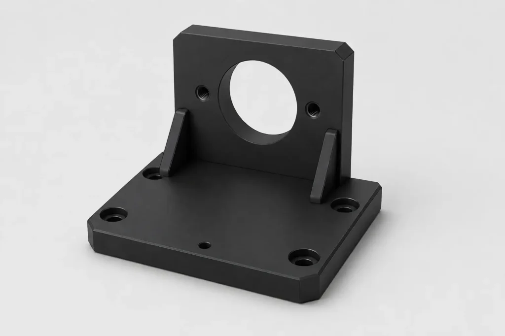
The completed components were supplied for customer assembly in the specified black-anodized condition.
The transferable result is not a single tolerance number. It is the process logic:
- Translate optical alignment requirements into measurable mechanical features
- Keep critical relationships tied to a stable datum structure
- Avoid locking final features before the main stock removal is complete
- Review anodizing before finalizing fitted dimensions
- Inspect each feature using a method appropriate to its function
This approach is more credible than claiming that every optical mount can hold the same tolerance or that black anodizing alone guarantees optical performance.
When This Machining Route Is Appropriate
This approach is suitable for optical and precision-instrument components that combine:
- A defined mounting face
- Datum-related hole patterns
- Locating bores or shoulders
- Multi-side machined features
- Black anodized surfaces
- Assembly-sensitive mechanical alignment
- Post-finish inspection requirements
It may also apply to sensor mounts, camera-system brackets, instrument frames and precision alignment fixtures.
The final manufacturing route must still be reviewed against the actual geometry, tolerance structure, material condition, quantity, finish and inspection requirements.
Buyer Checklist for an Optical Mount RFQ
Before requesting a quotation, provide:
- 3D CAD model
- Controlled 2D drawing
- Aluminum alloy and temper
- Primary, secondary and tertiary datums
- Critical mounting face
- Hole-pattern and fitted-feature requirements
- Definition of the mechanical feature representing the optical axis
- Mating-component information where available
- Optical-element support points and allowable clamping loads if the mount directly supports a sensitive optic
- Pre-anodize and post-anodize dimensional requirements
- Masking requirements
- Black anodizing specification
- Approved surface pretreatment where low-glare texture is required
- Cosmetic zones and acceptance expectations
- Cleanliness, particle, drying and packaging requirements where applicable
- Thread and fit-verification requirements
- Inspection-report and sampling requirements
- Prototype or production quantity
If the optical alignment requirement cannot yet be expressed mechanically, provide the assembly function and the failure mode that must be avoided. This gives the manufacturing team a better basis for DFM review.
Review Your Optical Mount Project
For a precision optical mount, the most important inputs are not only the nominal dimensions. The datum structure, mating components, alignment features, finishing state and inspection method must work together.
Review our precision machining support or send the drawing package and inspection requirements for project review.
Include the 3D model, 2D drawing, material, critical feature relationships, anodizing requirements, mating-component information and expected quantity.