Conclusion First
Thin-wall motor housings are among the most difficult aluminum CNC components to machine consistently.
The challenge is not simply machining outside dimensions. The real difficulty is maintaining:
- bearing bore concentricity
- wall stability after unclamping
- repeatable geometry in production
- vibration-free rotating alignment
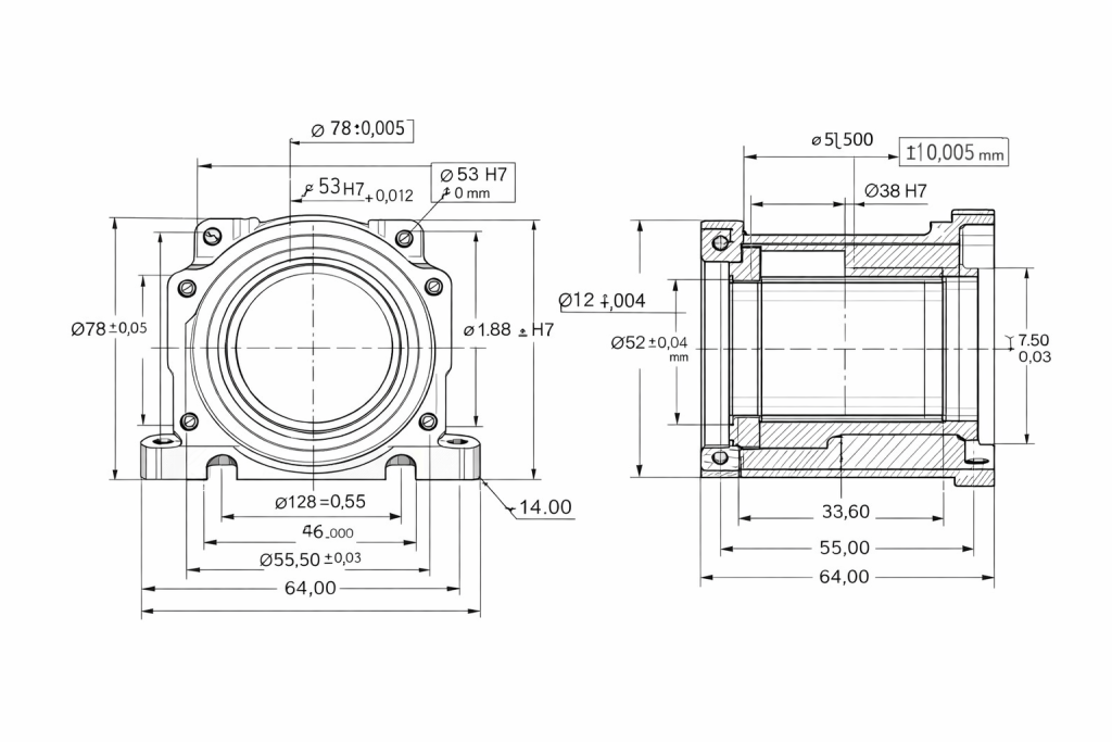
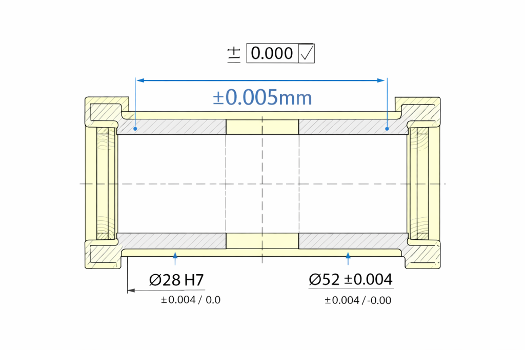
In this project, RapidEfficient machined a custom aluminum motor housing with 1.2–1.5 mm wall thickness while achieving ±0.005 mm concentricity on critical rotating features.
For engineers comparing material options first, read our Best Aluminum for Precision Machining Guide
Project Requirements
The customer required a lightweight housing for a precision drive system.
| Feature | Requirement |
|---|---|
| Material | 6061-T6 Aluminum |
| Wall Thickness | 1.2–1.5 mm |
| Bearing Bore Tolerance | H7 |
| Concentricity | ±0.005 mm |
| Surface Finish | Ra 0.8 μm |
| Batch Stability | Required |
The previous supplier could produce prototypes, but failed to maintain geometry consistently in production batches.
Why Thin-Wall Motor Housings Often Fail
Many shops can hold dimensions on a solid billet.
Thin-wall housings are very different.
Common failure points include:
- wall movement during clamping
- residual stress release after rough machining
- bore shift after unclamping
- chatter on weak wall sections
- poor alignment between front and rear bearing seats
This leads to real-world problems such as:
- bearing noise
- rotor vibration
- assembly rejection
- shortened service life
- unstable motor performance
Need tolerance guidance? Read our CNC Aluminum Tolerance Guide
Ordinary Process vs Our Process
Typical Low-Control Process
- heavy roughing and finishing in one cycle
- standard vise clamping
- no stress stabilization time
- separate setups for critical bores
- limited inspection after machining
Result:
- bore ovality
- concentricity drift
- wall distortion
- unstable batch consistency
RapidEfficient Controlled Process
- rough machining first
- stress release stabilization
- custom soft-jaw profile fixturing
- one-setup critical bore finishing
- full dimensional and CMM verification
Result:
- stable bore geometry
- controlled wall movement
- repeatable concentricity
- production-ready consistency
Our Machining Strategy
1. Stable Material Selection
We selected certified 6061-T6 aluminum with excellent machinability and predictable dimensional behavior.
6061 remains one of the best choices for precision housings without the higher cost of 7075.
2. Rough + Rest + Finish Sequence
The housing was rough-machined first, then allowed to stabilize before final finishing.
This reduced dimensional movement caused by internal stress.
3. Custom Soft-Jaw Fixturing
We machined custom jaws matching the housing profile.
This distributed pressure evenly and protected thin-wall areas during clamping.
4. One-Setup Bore Finishing
Critical bearing bores were finished in one controlled setup to preserve axis alignment.
This project also shows why datum control and tolerance stack-up analysis are critical for thin-wall motor housings, especially when bearing bores, sealing faces, and mounting holes must work together.
5. Thermal Awareness During Finishing
Aluminum has a relatively high thermal expansion coefficient:
α≈23.1×10⁻⁶/K
Even small temperature changes during machining can influence a thin wall section, so finishing parameters were carefully controlled.
6. Final CMM Verification
All key dimensions and concentricity values were inspected before shipment.
For micron-level machining methods, read our How to Achieve ±0.005mm in Aluminum Parts case study
For thin-wall motor housings, CMM inspection is essential to verify bore concentricity, datum alignment, and final assembly accuracy.
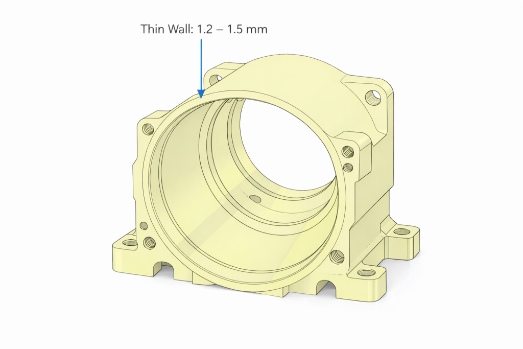
Thin Wall Control: Why It Matters
At 1.2–1.5 mm wall thickness, even small cutting forces or fixture imbalance can distort the housing.
That distortion may partially disappear after unclamping, making inspection results inconsistent.
Our process focused on:
- balanced toolpaths
- light finishing passes
- support near weak zones
- controlled cutting heat
- symmetrical material removal
These steps significantly improved repeatability.
Final Results
| Feature | Target | Achieved |
|---|---|---|
| Wall Thickness | 1.2–1.5 mm | Passed |
| Bearing Bore | H7 | Passed |
| Concentricity | ±0.005 mm | ±0.004 mm |
| Surface Finish | Ra 0.8 μm | Ra 0.6 μm |
| Batch Stability | Required | Passed |
Hidden Cost Buyers Often Ignore
Many buyers compare only unit price.
But poor concentricity creates much larger costs:
- motor noise complaints
- bearing replacement
- failed final assembly
- vibration troubleshooting
- warranty claims
- delayed product launch
The cheapest quote often becomes the most expensive production run.
Need pricing guidance? Read our Aluminum Machining Cost Guide
Best Fit Applications
This type of housing is ideal for:
- BLDC motor housings
- servo motor housings
- robotics drive systems
- precision spindle housings
- automated motion-control assemblies
Engineer’s Note
For motor housings, geometry matters more than cosmetic appearance.
A clean external finish cannot compensate for a misaligned rotating system.
When bearing bores drift, the motor reveals the truth immediately.
FAQ
Why is concentricity important in motor housings?
Poor concentricity causes vibration, noise, and premature bearing wear.
Can thin-wall aluminum housings be machined reliably?
Yes—when fixture design, machining sequence, and inspection control are properly managed.
Why do thin-wall parts deform?
Because clamping force, cutting heat, and internal stress can move weak wall sections.
Is 6061 good for motor housings?
Yes. It offers an excellent balance of machinability, strength, corrosion resistance, and cost.
What causes motor housing vibration?
Common causes include poor concentricity, bearing misalignment, imbalance, and weak assembly control.
How thin can aluminum motor housings be machined?
It depends on geometry and tolerance requirements, but 1.2 mm walls are achievable with proper process control.
Need Precision CNC Motor Housings?
RapidEfficient supplies custom housings for:
- robotics
- EV systems
- automation equipment
- drive systems
Send us your drawing today.
Our engineers will review manufacturability, tolerance feasibility, and cost-saving opportunities before production.