CNC 铝光学安装座加工案例研究

快速解答

RapidEfficient machined a 6061-T6 aluminum optical mount whose manufacturing risk was concentrated in the relationship between its mounting face, 孔型, locating features and black-anodized final condition. The process was organized around datum control, 低变形工件夹具, coordinated machining of related features, finish allowance and feature-specific inspection.


项目概况

This was an earlier RapidEfficient project for a custom optical mount used in precision instrumentation.

项目项目描述
成分CNC-machined optical mount
材料6061-T6铝
最终完成Matte black anodize
功能优先级Mounting-face stability, hole-pattern relationships and repeatable mechanical location
Manufacturing risks数据传送, 钳位畸变, multi-side machining and coating buildup
检查重点安装面, 定位特征, fitted interfaces and post-finish condition

保护客户机密, 未公开识别信息和选定的图纸尺寸.

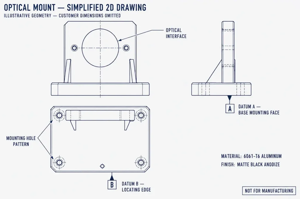
Simplified 2D engineering drawing of a 6061-T6 aluminum optical mount showing Datum A, 日期 B, the optical interface, and mounting hole pattern

The challenge was not simply producing an aluminum bracket with accurately machined holes. The part had to preserve the mechanical relationships used to locate the optical assembly.


Why an Optical Mount Is More Than a Precision Bracket

An optical mount transfers mechanical variation into the assembled optical system.

然而, the relationship is more complex than saying that every dimensional error creates the same amount of optical error. The actual effect depends on the optical layout, lever arm, lens or sensor position, mating components and calibration method.

Our manufacturing responsibility was therefore to control the mechanical interfaces defined on the drawing:

  • The primary mounting face
  • Locating edges or shoulders
  • Hole patterns related to assembly datums
  • Fitted bores or locating features
  • 螺纹安装点
  • Surfaces affected by anodizing
  • Cosmetic areas visible after assembly

Flatness alone does not control the orientation of one feature relative to another. A mounting face can meet its flatness requirement while a bore, hole pattern or locating shoulder is still incorrectly oriented.

同样地, a hole can meet its size limit while its location relative to the mounting datum is incorrect.

The optical axis therefore had to be translated into measurable mechanical features before machining began.

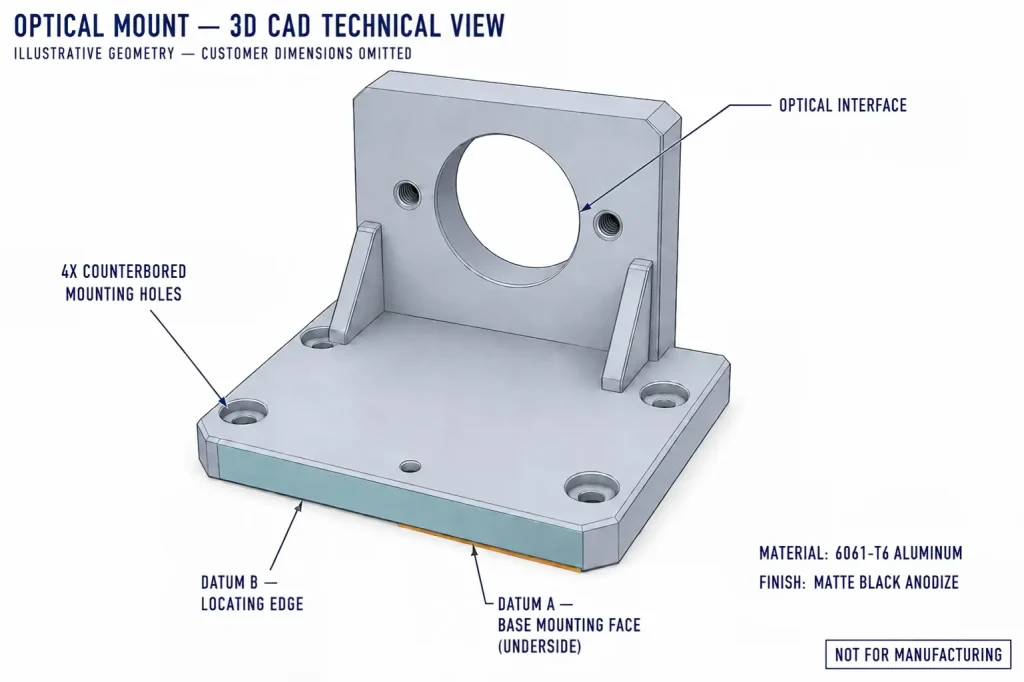
Annotated 3D CAD view of a 6061-T6 aluminum optical mount showing the optical interface, four mounting holes, 基准A, and Datum B

If the mount directly supports a sensitive lens, mirror or other optical element, the drawing should also define the support points, contact geometry and allowable clamping load. These are system-design requirements and should not be inferred from the machined-part geometry alone.


主要制造风险

The project review separated each functional feature from the failure it could create during assembly.

特征制造风险Procurement or Assembly Consequence
主安装面Clamping pressure or stock removal changes its free-state form摇摆, uneven seating or orientation error
与基准相关的孔阵列Setup transfer changes the relationship to the mounting faceDifficult assembly or inconsistent component location
Fitted bore or locating featureSize changes after finishingLoose fit, interference or loss of repeatability
Multi-side featuresDifferent setups establish conflicting referencesAccumulated positional error
Threads and counterboresCoating buildup or burrs affect engagementFastener seating or thread-acceptance problems
Matte black finishPretreatment exposes tool marks or creates appearance variationCosmetic rejection or inconsistent surface condition

This analysis prevented the process from treating every dimension as equally critical.

The most important characteristics were the relationships controlling assembly. Non-critical exterior dimensions and cosmetic envelopes did not need the same machining and inspection effort.


DFM Review Focused on the Datum Structure

The drawing review started with a simple question:

Which physical surfaces and features locate the optical assembly?

A reliable datum structure should correspond to real, accessible features that can be used during machining, inspection and assembly.

For this type of optical mount, the review should identify:

  1. The primary mounting surface
  2. The secondary locating edge or feature
  3. The feature preventing the remaining degree of movement
  4. The hole pattern related to those datums
  5. Any fitted bore, shoulder or optical-interface feature
  6. Whether the final requirement applies before or after anodizing

A coordinate dimension by itself does not always protect the functional relationship. Where appropriate, 位置, 垂直度, parallelism or profile controls may communicate the requirement more clearly.

The correct control depends on the assembly. GD&T should protect function rather than decorate the drawing.

For broader guidance on assigning realistic feature-level requirements, 回顾我们的 CNC加工公差指南.


Machining Route for the Optical Mount

We Established the Manufacturing References First

The initial operation created stable machining references before the critical multi-side features were finished.

The manufacturing datum did not have to copy the final design datum blindly. It had to provide stable support, repeatable location and access to the features required in later operations.

The route was planned so that the final functional relationships could still be traced back to the drawing datum structure.

We Avoided Forcing the Part Into a False Shape

Excessive clamping pressure can make a component appear stable during cutting while storing elastic deformation in the part.

松开夹具后, the component can move toward its free-state shape.

The workholding strategy therefore had to:

  • Support rigid areas of the component
  • Distribute clamping force
  • Avoid loading slender walls or unsupported sections
  • Keep chips away from locating surfaces
  • Provide repeatable access for subsequent operations
  • Allow the part to be checked after release

The objective was not maximum clamping force. It was sufficient restraint without changing the geometry being manufactured.

We Removed the Main Stock Before Final Feature Control

Heavy material removal and final precision finishing were not treated as the same operation.

The main stock was removed before the final mounting and locating relationships were locked. This allowed the component to release most of the movement associated with machining before the final feature-control stage.

取决于几何形状, a suitable route may include:

  • 粗加工
  • 受控库存津贴
  • Part release
  • Re-establishment of the datum system
  • 半精加工
  • Final feature machining
  • 自由状态检验

The exact sequence depends on the part geometry, stock form and drawing requirements.

We Kept Related Features Together Where Practical

Every unnecessary setup transfer introduces another opportunity for location error.

实用的地方, features sharing a functional relationship were finished without unnecessary datum transfer.

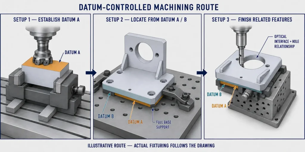
Three-step datum-controlled machining route for an aluminum optical mount showing Datum A establishment, Datum A/B locating, and related-feature finishing

This did not mean that every surface had to be machined in one setup. It meant that the process prioritized the relationships that mattered most.

例如, a mounting face and its related hole pattern may justify coordinated machining or probing. An unrelated cosmetic pocket may not.

We Controlled Burrs Around Assembly Features

Burrs around locating holes, counterbores and threaded features can create false seating even when the measured dimensions appear acceptable.

Deburring therefore had to remove loose or raised material without:

  • Enlarging fitted holes
  • Rounding functional datum edges
  • Damaging thread starts
  • Changing counterbore seating surfaces
  • Creating inconsistent cosmetic edge breaks

The objective was controlled edge condition, not aggressive polishing.


Preparing the Part for Matte Black Anodizing

Black anodizing was part of the specified final condition, but the coating could not be treated as a purely cosmetic operation.

Anodizing changes the surface of the aluminum and can affect:

  • Fitted hole size
  • 螺纹啮合
  • Counterbore seating
  • Locating shoulders
  • 配合面
  • 电气接触区域
  • Cosmetic texture and shade

The drawing therefore needed to clarify which requirements applied:

  • 阳极氧化前
  • 阳极氧化后
  • 在遮蔽表面上
  • 螺纹或配合验证后

Masking is not automatically required on every optical mount. It should only be specified where coating buildup would interfere with fit, 接触, assembly or another functional requirement.

If a low-glare texture is required, the drawing should define the approved pretreatment and identify functional faces, fitted holes and datum features that must be protected from blasting. A fixed blasting medium or masking route should not be assumed without a released specification.

Matte black appearance also does not define optical reflectance by itself. If stray-light performance is critical, the drawing or specification should state the required optical property, approved finish or acceptance method rather than relying only on the word “black.”

Cleanliness requirements must also be defined where the component will be used near sensitive optics. Particle limits, approved cleaning methods, drying conditions and packaging expectations should come from the project specification rather than being inferred from the anodizing color.

For a wider comparison of coating behavior and drawing requirements, 回顾我们的 铝阳极氧化和粉末涂层指南.


Inspection Had to Match the Functional Relationship

A single CMM report does not prove every aspect of an optical mount.

The inspection method must match the feature and its function.

Inspection FeatureWhat Must Be VerifiedAppropriate Inspection Logic
主安装面Surface form in the required released or supported stateEvaluate flatness independently of any datum reference
Mounting-face orientationRelationship to another specified featureEvaluate parallelism or perpendicularity relative to the drawing datum where required
与基准相关的孔阵列Location and orientation relative to the drawing datumsCMM alignment to the specified datum reference frame
Fitted bore or locating feature尺寸, form and assembly condition内径规, 塞规, CMM or functional fit check as appropriate
线程数Engagement and coating influenceGO/NO-GO thread gauge after the required finishing stage
Counterbores and fastener seats直径, depth and seating conditionDimensional measurement and visual edge review
阳极氧化外观覆盖范围, texture and agreed cosmetic conditionVisual inspection under defined lighting and viewing conditions
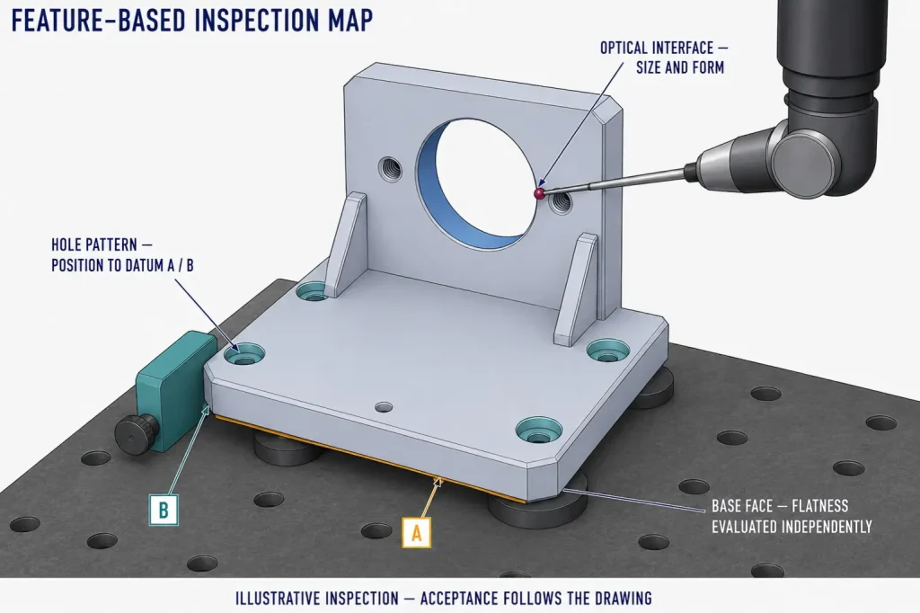
Feature-based CMM inspection map for an aluminum optical mount showing bore contact, hole position to Datum A/B, and independent base-face flatness evaluation

Flatness controls only the form of the selected surface. It does not reference Datum A, 乙或丙.

If the mounting face must remain parallel or perpendicular to another feature, the drawing needs a separate orientation control.

The hole pattern can be evaluated relative to a specified datum reference frame, but the inspection alignment must reproduce the drawing logic rather than use an arbitrary best-fit coordinate system.

同样地, fitted features need more than a reported center coordinate. 尺寸, 形式, coating state and functional fit can all affect assembly.

Where documented production evidence is required, the drawing and purchase order should define the expected dimensional report, sampling plan and 首件检验 requirements before machining begins.


项目成果

RapidEfficient completed the optical-mount project using a machining route built around datum relationships, controlled workholding, finishing-state planning and feature-specific inspection.

The completed components were supplied for customer assembly in the specified black-anodized condition.

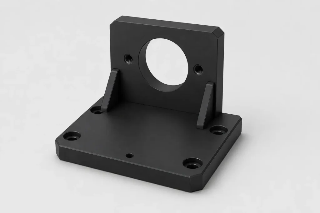
Illustrative matte black anodized aluminum optical mount with a circular interface, four counterbored mounting holes, 定位孔, and reinforced base

The transferable result is not a single tolerance number. It is the process logic:

  • Translate optical alignment requirements into measurable mechanical features
  • Keep critical relationships tied to a stable datum structure
  • Avoid locking final features before the main stock removal is complete
  • Review anodizing before finalizing fitted dimensions
  • Inspect each feature using a method appropriate to its function

This approach is more credible than claiming that every optical mount can hold the same tolerance or that black anodizing alone guarantees optical performance.


该加工路线何时合适

This approach is suitable for optical and precision-instrument components that combine:

  • A defined mounting face
  • 与基准相关的孔阵列
  • Locating bores or shoulders
  • Multi-side machined features
  • Black anodized surfaces
  • Assembly-sensitive mechanical alignment
  • Post-finish inspection requirements

It may also apply to sensor mounts, camera-system brackets, instrument frames and precision alignment fixtures.

The final manufacturing route must still be reviewed against the actual geometry, tolerance structure, 物质条件, 数量, finish and inspection requirements.


Buyer Checklist for an Optical Mount RFQ

在请求报价之前, 提供:

  • 3CAD模型
  • 受控二维绘图
  • 铝合金及状态
  • 基本的, secondary and tertiary datums
  • Critical mounting face
  • Hole-pattern and fitted-feature requirements
  • Definition of the mechanical feature representing the optical axis
  • Mating-component information where available
  • Optical-element support points and allowable clamping loads if the mount directly supports a sensitive optic
  • Pre-anodize and post-anodize dimensional requirements
  • 遮蔽要求
  • Black anodizing specification
  • Approved surface pretreatment where low-glare texture is required
  • Cosmetic zones and acceptance expectations
  • 清洁度, particle, drying and packaging requirements where applicable
  • Thread and fit-verification requirements
  • 检验报告和抽样要求
  • 原型或生产数量

If the optical alignment requirement cannot yet be expressed mechanically, provide the assembly function and the failure mode that must be avoided. This gives the manufacturing team a better basis for DFM review.


Review Your Optical Mount Project

For a precision optical mount, the most important inputs are not only the nominal dimensions. The datum structure, 配合组件, 对准特征, finishing state and inspection method must work together.

回顾我们的 精密加工支持 或者 发送图纸包和检验要求 for project review.

Include the 3D model, 2D图, 材料, critical feature relationships, 阳极氧化要求, mating-component information and expected quantity.

发表评论

滚动至顶部

获取报价

点击或拖拽文件到该区域即可上传. 您最多可以上传 10 文件.
文件格式:TXT PDF DOC DOCX XLS XLSX PPT PPTX JPG PNG ZIP RAR DWG DXF DXF DWT DWS DWS

3D文件格式: 步, STP, sldprt, IPT, prt, 坐着, IGES, IGS, catpart, X_T, OBJ, STL