CNC 加工铝材表面光洁度指南 | 达到Ra 0.8

REPRESENTATIVE CASE STUDY

Achieving Ra 0.8 on Critical Surfaces of a CNC-Machined Aluminum Housing

This case shows how surface-finish requirements were divided by part function and connected to machining, 夹具, 检查, 阳极氧化, and handling decisions.

The drawing and CAD views use simplified, non-customer-identifying project details to explain the engineering process.

Project Overview

The project focused on a CNC-machined aluminum housing with different surface-finish requirements on different functional areas.

Project ItemRepresentative Specification
PartPrecision CNC-machined aluminum housing
材料铝6061-T6
Reference Size大约 120 × 80 × 55 毫米
Main ProcessCNC milling with multiple machining and inspection stages
Critical Surface Finish拉 0.8 μm
Controlled Functional Surfaces拉 1.6 μm
General Machined Surfaces拉 3.2 μm 除非另有说明
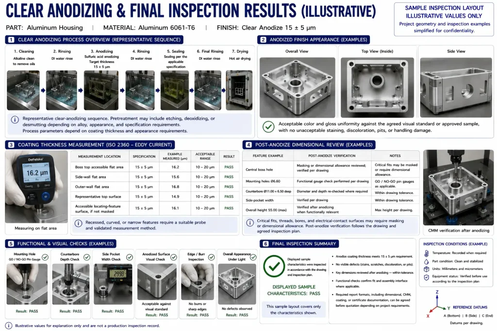
表面处理Clear anodizing, nominally 15 ± 5 μm
检查Surface-roughness inspection and dimensional verification
Main Risks内置边缘, chip scratches, 颤痕, inconsistent finishing allowance, and finish damage during handling

The main goal was not to make every surface equally smooth.

The surface-finish plan had to distinguish between critical mating areas, controlled internal surfaces, and general non-critical faces. This avoided unnecessary finishing work while keeping the important functional areas under tighter control.


Customer and Drawing Requirements

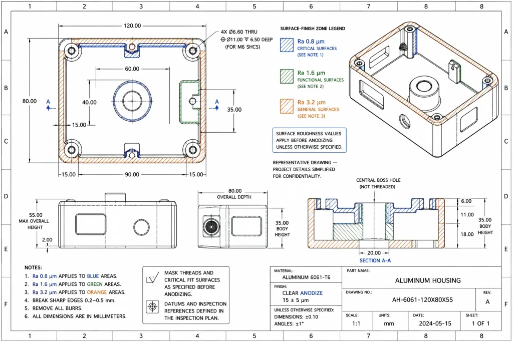
The drawing divided the housing into three surface-finish zones.

拉 0.8 μm: Critical Surfaces

拉 0.8 μm was assigned only to selected functional areas where surface condition could affect mating, 密封, 定位, or inspection.

These surfaces required:

  • A controlled finishing pass
  • 稳定的刀具啮合
  • Protection from chip scratches
  • Profilometer inspection
  • Clear identification on the drawing and inspection plan

拉 1.6 μm: Controlled Functional Surfaces

拉 1.6 μm was used for internal or functional surfaces that required a consistent machined finish but did not need the same level of control as the critical faces.

拉 3.2 μm: General Machined Surfaces

拉 3.2 μm was used as the general requirement for non-critical machined areas unless another value was specifically shown.

The drawing also included:

  • Aluminum 6061-T6 material
  • Counterbored mounting holes
  • Internal bores and pockets
  • Burr and sharp-edge removal
  • Clear anodizing
  • General dimensional tolerances

A roughness value does not automatically define appearance. Two surfaces with the same Ra can still have different tool marks, 划痕, waviness, lay direction, and reflectivity.

Representative 2D engineering drawing of a 6061-T6 CNC aluminum housing showing Ra 0.8, 拉 1.6, and Ra 3.2 surface zones, 120 by 80 经过 55 millimeter dimensions, M6 counterbored mounting holes, and clear anodizing requirements.

Surface-Finish Planning in the 3D Model

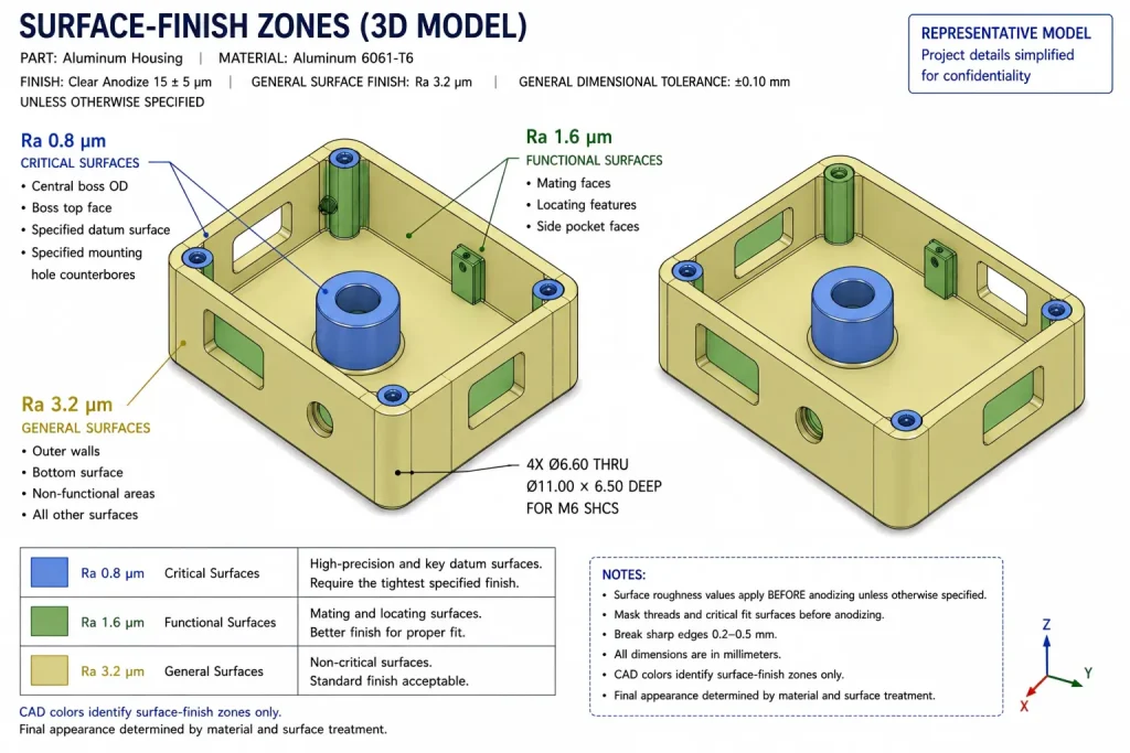
机加工前, the housing surfaces were reviewed by function.

The 3D model was used to separate:

  • Critical Ra 0.8 表面
  • Controlled Ra 1.6 表面
  • General Ra 3.2 表面
  • Features requiring protection during later setups
  • Areas where chip accumulation could damage an already finished face

This prevented the complete component from being treated as if every surface had the same requirement.

The CAD review also helped identify:

  • Tool-access restrictions
  • 内角
  • Long-reach areas
  • Large flat surfaces
  • Bore and pocket relationships
  • Surfaces that could be marked by clamping
  • Areas affected by anodizing or masking

CAD display colors are used only to distinguish surface zones. They do not represent the final color of the clear-anodized component.

Two representative 3D CAD views of a 6061-T6 aluminum housing showing Ra 0.8 临界面, 拉 1.6 功能表面, and Ra 3.2 general machined areas.

Why 6061-T6 Was Used for the Housing

6061-T6 is a practical material for machined housings because it provides a useful balance of:

  • 力量
  • 耐腐蚀
  • 材料可用性
  • 机械加工性
  • Anodizing options
  • 重量
  • 成品成本

然而, the material alone does not guarantee Ra 0.8.

6061 can still develop:

  • 内置边缘
  • 涂抹
  • 毛刺
  • Long or adhesive chips
  • Surface scratches caused by chip recutting

The finishing result depends on tooling, 跳动, workholding, 芯片控制, 加工顺序, 和检查.

For projects requiring a comparison with higher-strength 7075, 回顾我们的 6061 与 7075 铝导轨.


主要制造挑战

1. Built-Up Edge on the Cutting Tool

Aluminum can adhere to the cutting edge and change the effective tool geometry.

This may leave:

  • Torn areas
  • 涂抹
  • 毛刺
  • Unstable tool marks
  • Local changes in surface roughness

The risk becomes more important during the final pass because a small amount of adhered material can damage an otherwise acceptable surface.

2. Chip Recutting Inside the Housing

The internal pocket and walls can retain loose aluminum chips.

If these chips remain in the cutting zone, they may:

  • Scratch a finished surface
  • Become trapped beneath the tool
  • Damage internal walls
  • Create random marks that are not visible in the programmed toolpath

Chip removal therefore had to be planned before each critical finishing pass.

3. Chatter on Walls and Large Flat Surfaces

Long tool reach, unstable engagement, weak support, and excessive overhang can leave periodic vibration marks.

The risk is not limited to appearance. Chatter may also affect:

  • 平整度
  • Bore geometry
  • 边缘质量
  • 工具寿命
  • Dimensional consistency

4. Inconsistent Finishing Allowance

A finishing tool cannot cut consistently if some areas retain too much stock while other areas have almost no material left.

An inconsistent allowance can cause the tool to alternate between cutting and rubbing.

5. Protecting Finished Surfaces

A surface may meet the machining requirement and still be damaged during:

  • 去毛刺
  • 打扫
  • Part transfer
  • 阳极氧化
  • 检查
  • 包装

The process therefore had to include both machining control and post-machining surface protection.

For additional information about built-up edge, 芯片, flank wear, and tool replacement, 回顾我们的 CNC tool-wear guide.


Why a Standard One-Pass Strategy Was Not Enough

A simple machining approach might use the same tool, 精加工津贴, and cutting condition across every surface.

That approach can create several risks:

  • A roughing tool may already have edge wear before the critical finishing pass.
  • One feed and speed combination may not suit the top face, pocket floor, 墙壁, and bores.
  • Chips may remain inside the housing and scratch completed areas.
  • Critical surfaces may be finished too early and damaged during a later setup.
  • Surface-roughness inspection may occur only after all parts are complete.
  • Unnecessary fine finishing may be applied to non-critical areas.

The project therefore required a surface-specific process rather than one uniform finish strategy.


Optimized Machining and Fixturing Strategy

1. Separate Roughing and Finishing

Roughing removed most of the material while leaving a controlled allowance on the specified finish zones.

Critical surfaces were finished only after:

  • Major stock removal was complete
  • The part had reached a more stable condition
  • The fixture and datum surfaces were cleaned
  • The finishing tool had been checked

2. Use a Dedicated Finishing Tool

The final Ra-controlled surfaces were not automatically finished with the same worn cutting edge used for heavy roughing.

The finishing tool was selected to provide:

  • A sharp edge
  • Suitable aluminum-cutting geometry
  • Low runout
  • Practical reach
  • 稳定的排屑

3. Control Tool Overhang and Runout

Tool overhang was kept as short as the geometry allowed.

Before critical finishing, the process required checking:

  • Toolholder cleanliness
  • Spindle-taper contact
  • 刀具跳动
  • 尖端条件
  • Tool length and reach
  • 夹具稳定性

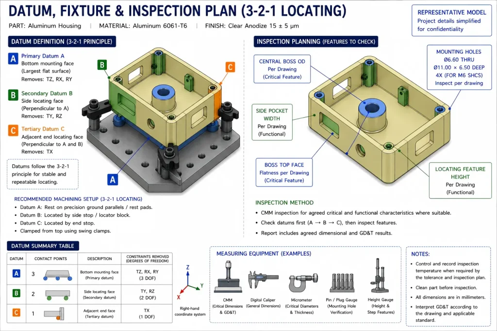
4. Support the Housing Without Marking Critical Surfaces

The fixture needed to locate the part from functional datums while distributing clamping force.

The support plan had to avoid:

  • Local wall deformation
  • Jaw marks
  • Part movement
  • Blocking tool access
  • Contact with completed Ra-controlled surfaces

5. Plan the Finishing Sequence

The sequence prioritized surfaces according to function and damage risk.

A practical order included:

  1. 粗加工
  2. Datum and reference-feature preparation
  3. Semi-finishing
  4. Critical Ra 0.8 精加工
  5. Remaining controlled surfaces
  6. Deburring and controlled cleaning
  7. Roughness and dimensional inspection

6. Remove Chips Before Critical Passes

The cavity, 钻孔, 口袋, and fixture contact surfaces were cleaned before the critical finishing operations.

An appropriate air, 冷却液, or lubrication strategy was used to reduce chip recutting without creating unstable thermal conditions.

代表 3-2-1 datum, 夹具, and inspection plan for a 6061-T6 CNC aluminum housing showing datum A B C, support and clamping, 关键特征, and measurement methods.

Surface-Roughness Inspection

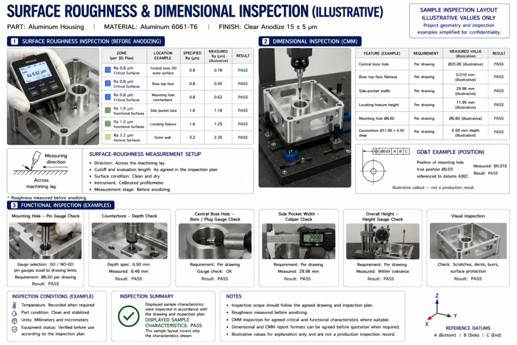
Surface roughness was treated as a separate inspection characteristic rather than judged only from visual appearance.

Before measurement:

  • The surface was cleaned.
  • The inspection location was matched to the drawing.
  • The stylus direction was selected relative to the machining lay.
  • The required Ra value was confirmed.
  • The instrument settings and evaluation length were recorded when required.

The Ra 0.8, 拉 1.6, and Ra 3.2 zones were evaluated separately.

A surface could not be accepted only because it appeared bright or reflective. 工具痕迹, 划痕, waviness, and local defects also required visual review.

Ra records an average profile value. For sealing or contact surfaces, the drawing may also need to control Rz, waviness, lay direction, or isolated surface defects.

Dimensional inspection remained separate from roughness inspection. A surface can meet its Ra requirement while the related bore, plane, or feature still fails dimensional or geometric tolerance.

Representative surface roughness and dimensional inspection layout for a CNC aluminum housing showing profilometer measurement, 三坐标检测, GO and NO-GO pin gauges, depth and dimensional checks, and visual inspection.

Clear Anodizing and Surface Protection

The representative drawing specifies clear anodizing after machining.

The anodizing requirement had to be reviewed together with:

  • 表面粗糙度
  • Bore and thread dimensions
  • 关键配合
  • 掩蔽
  • 电接触区域
  • 密封面
  • 化妆品的期望
  • Final inspection condition

Clear anodizing does not automatically hide machining marks.

喋喋不休, 划痕, 凹痕, and inconsistent tool paths may remain visible after treatment. The machined surface therefore had to be acceptable before anodizing.

The drawing should also define whether the Ra requirement applies:

  • 阳极氧化前
  • 阳极氧化后
  • Or at both stages

线程数, 钻孔, and close-fit surfaces may require masking or machining allowance depending on the functional requirement.

Representative clear anodizing and final inspection layout for a 6061-T6 CNC aluminum housing showing the anodizing sequence, coating thickness measurement, post-anodize dimensional review, functional checks, and visual inspection.

What This Project Demonstrates

The main lesson was not that every aluminum surface should be machined to Ra 0.8.

The project showed that better results come from connecting each drawing requirement to a specific process step.

The control plan separated:

  • Critical and non-critical surfaces
  • Roughing and finishing tools
  • Machining and inspection requirements
  • Functional dimensions and cosmetic appearance
  • Machining quality and post-machining protection

This approach helps avoid two opposite problems:

Overprocessing a general surface that does not require a premium finish

Under-controlling a critical mating or sealing surface


FAQ About This Aluminum Surface-Finish Case

能 6061 Aluminum Be Machined to Ra 0.8 μm?

是的, suitable 6061 features can achieve Ra 0.8 μm under a stable process.

The result depends on tool condition, 跳动, 夹具稳定性, 精加工津贴, 排屑, feature access, 及测量方法.

Does Ra 0.8 Mean a Mirror Finish?

福田街道.

Ra describes average profile roughness. It does not directly define reflectivity, waviness, lay direction, 划痕, 或美容外观.

Should Every Surface Be Specified as Ra 0.8?

福田街道.

Only surfaces with a functional or justified cosmetic requirement should receive a tighter roughness specification. General non-critical surfaces may use a less demanding finish.

Is Surface Roughness Measured Before or After Anodizing?

The drawing or inspection plan should define the required condition.

Anodizing can affect surface texture and dimensions, so the requirement should not be left open to interpretation.

Can Surface Finish Be Confirmed by Looking at the Part?

Visual inspection can identify tool marks, 划痕, 凹痕, and appearance differences, but it cannot confirm a specified Ra value.

A suitable surface-roughness instrument is required.


Review Your Aluminum Housing Before Production

Send the STEP file, 2D图, aluminum alloy and temper, required Ra or Rz values, surface-treatment requirement, 关键尺寸, 数量, 及检验要求.

Rapid Efficient can review:

  • Surface-finish zones
  • 工具访问
  • 精加工余量
  • Fixturing and support
  • Chip-control risks
  • Anodizing and masking
  • Roughness inspection
  • 尺寸检验
  • Handling and packaging

适用于定制铝制外壳, 括号, 盘子, 固定装置, 及精密零件, 回顾我们的 CNC铝加工服务.
发表评论

滚动至顶部

获取报价

点击或拖拽文件到该区域即可上传. 您最多可以上传 10 文件.
文件格式:TXT PDF DOC DOCX XLS XLSX PPT PPTX JPG PNG ZIP RAR DWG DXF DXF DWT DWS DWS

3D文件格式: 步, STP, sldprt, IPT, prt, 坐着, IGES, IGS, catpart, X_T, OBJ, STL