数控加工中的刀具磨损: 类型, 原因, 和预防

快速解答: 如何减少数控刀具磨损?

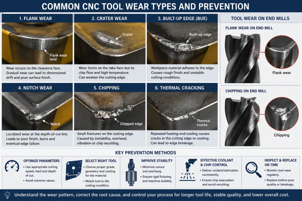
数控加工中的主要刀具磨损模式包括后刀面磨损, crater wear, 积屑瘤, notch wear, 边缘碎裂, plastic deformation, coating flaking, and thermal cracking.

The correct prevention method depends on the visible wear pattern.

Common starting actions include:

  • Reducing excessive cutting speed when heat-related wear develops
  • Correcting feed and depth of cut rather than reducing every parameter
  • Selecting a tool grade and geometry suited to the workpiece
  • Reducing tool overhang and runout
  • Improving fixture and machine stability
  • Preventing chips from being cut again
  • Delivering coolant or lubrication consistently
  • 避免摩擦, dwelling, and unstable tool engagement
  • Replacing the tool before wear causes dimensional drift or edge failure

A worn tool should not be diagnosed only by total cutting time. Examine where the damage appears, whether it is uniform, how the chips look, and whether surface finish, 切削力, sound, 温度, or part dimensions have changed.

Flank wear is often the most predictable wear pattern, while random chipping or catastrophic fracture usually indicates instability, overload, 切屑再切削, or an ignored earlier wear condition.

Carbide inserts and end mills showing flank wear, crater wear, built-up edge, notch wear, chipping, thermal cracking, and key CNC tool wear prevention methods.

1. Common Tool-Wear Patterns in CNC Machining

Tool wear is the gradual deterioration of a cutting edge during contact with the workpiece and chip.

Some wear is expected. The objective is not to eliminate every visible wear mark, but to develop a predictable process in which the tool reaches a planned replacement point before it damages the part or fails unexpectedly.

Tool-Wear Diagnosis Table

Wear PatternWhere It AppearsCommon SymptomsCommon Starting Actions
Flank wearClearance face along the cutting edgeGradual dimensional drift, higher cutting force, dull edge, 糟糕的完成Review cutting speed, 年级, 冷却剂输送, and replacement interval
月牙洼磨损Rake face where the chip flowsA depression behind the edge, weakened edge, eventual breakageReduce excessive speed or heat, review grade, 几何学, 喂养, and coolant
内置边缘Workpiece material attached to the cutting edgeRough or torn finish, 尺寸不稳定, material periodically breaking awayUse sharper geometry, improve lubrication, adjust speed, 并防止摩擦
缺口磨损Localized area near the depth-of-cut lineGroove at one point, 毛刺, 糟糕的完成, local edge failureVary depth of cut, review grade and geometry, reduce rubbing and excessive heat
碎屑Small irregular fractures along the edgeSudden poor finish, 噪音, 振动, unpredictable tool lifeImprove rigidity, shorten overhang, reduce runout, prevent chip recutting
Plastic deformationCutting edge becomes rounded, depressed, or displacedRapid loss of geometry, high force, dimensional errorReduce heat and load, use a more deformation-resistant grade
Thermal crackingRepeated cracks, often across the cutting edgeComb-like cracks, edge fragments, sudden failureStabilize thermal conditions and review intermittent coolant application
Coating flakingCoating separates from the substrateExposed substrate, accelerated wear, irregular edge conditionReview coating compatibility, 边缘准备, 附着力, and cutting stability
Catastrophic fractureLarge part of the insert or tool breaksImmediate tool failure, possible workpiece or machine damageStop and check overload, collision, 稳定, 排屑, and previous wear

Flank Wear

Flank wear develops on the clearance face where the tool rubs against the newly machined surface.

Relatively uniform flank wear is usually more predictable than random chipping. 然而, rapid flank wear may indicate excessive cutting speed, an unsuitable grade, abrasive material, poor coolant delivery, or a worn coating.

Because the worn flank contacts the finished surface, it may gradually affect:

  • Part diameter
  • 表面光洁度
  • 切削力
  • Tool compensation
  • 尺寸一致性

Crater Wear

Crater wear forms on the rake face where hot chips flow over the tool.

It is associated with heat, diffusion, chemical interaction, and abrasion. If the crater becomes too deep, the remaining cutting edge becomes weak and may chip or break.

Crater wear should not automatically be solved by reducing feed. 取决于几何形状, a feed that is too low may increase rubbing and contact time.

累积边缘

Built-up edge occurs when workpiece material adheres to the cutting edge.

It is common with ductile or adhesive materials and may cause:

  • Torn surfaces
  • 毛刺
  • Unstable effective tool geometry
  • Dimensional variation
  • Edge damage when the deposited material breaks away

Built-up edge is not simply normal abrasive wear. It usually indicates an interaction between material adhesion, 工具锋利度, 切割速度, 润滑, and chip flow.

Notch Wear

Notch wear is concentrated near the depth-of-cut line.

It can develop when the surface layer is harder or work-hardened, when scale or oxidation is present, or when the same point on the cutting edge repeatedly contacts the workpiece surface.

Changing the depth of cut between passes may help move the contact point rather than forcing the same area of the tool to carry every cut.

Chipping and Fracture

Chipping is usually less predictable than uniform wear.

常见原因包括:

  • 跳动过大
  • 刀具悬伸
  • Weak workholding
  • 喋喋不休
  • 断续切割
  • Incorrect entry into the material
  • Chips being recut
  • An edge that is too sharp or too brittle for the load
  • Excessive feed or depth of cut
  • Collision

Complete fracture should be treated as a process failure rather than an acceptable tool-life endpoint.

Plastic Deformation and Thermal Cracking

Plastic deformation occurs when high cutting pressure and temperature cause the edge to lose its intended shape.

Thermal cracks can develop when a tool repeatedly heats and cools, especially in interrupted operations such as milling.

Coolant is not automatically the solution in every process. Inconsistent coolant delivery may create larger temperature cycles than stable dry cutting or consistent flood delivery.

Sandvik classifies flank wear, crater wear, 积屑瘤, notch wear and plastic deformation by their dominant wear mechanisms, while Seco also identifies chipping, coating flaking, thermal cracking and catastrophic fracture as distinct troubleshooting patterns.


2. What Causes Rapid or Unstable Tool Wear?

切割速度

Cutting speed strongly affects cutting-zone temperature.

When speed is too high for the tool grade and material, it may accelerate:

  • Flank wear
  • 月牙洼磨损
  • Plastic deformation
  • Diffusion-related wear
  • Coating breakdown

然而, a cutting speed that is too low may also cause built-up edge, rubbing, unstable chip formation, or chatter.

The correct response depends on the observed wear pattern.

Feed and Depth of Cut

Feed and depth of cut control chip thickness and cutting load.

Excessive values may cause:

  • Mechanical overload
  • 碎屑
  • Deflection
  • 排屑不良
  • 夹具移动
  • 刀具破损

Values that are too low can also be harmful by causing:

  • Rubbing instead of cutting
  • 内置边缘
  • Excessive contact time
  • 加工硬化
  • Rapid wear concentrated in a small area

Do not reduce speed, 喂养, and depth of cut together without identifying the failure mechanism.

Tool Grade, 几何学, and Coating

Tool selection must match:

  • 工件材料
  • 硬度
  • 连续或断续切削
  • Roughing or finishing
  • 机械刚性
  • 刀具悬伸
  • Coolant condition
  • 生产数量

A harder, more wear-resistant grade may resist flank wear but chip under an unstable interrupted cut.

A tougher grade may resist chipping but wear faster under continuous abrasive cutting.

Tool coatings are also application-specific. 锡, 氮化钛, 金子, DLC, 钻石, and uncoated polished tools should not be ranked using one universal list.

For a broader comparison of toughness, 戴阻力, 切割速度, and tool cost, 查看我们的指南 high-speed steel vs carbide tools.

跳动, Overhang, and Rigidity

Excessive runout causes one cutting edge to remove more material than the others.

This can create:

  • Uneven flute wear
  • 碎屑
  • 振动
  • 表面光洁度差
  • 过大或不一致的特征
  • Short tool life

Long tool overhang reduces stiffness and increases deflection. Use the shortest practical tool and holder combination that still reaches the feature.

The fixture, spindle, 持有者, collet, insert seat, pull stud, and tool shank should all be checked when wear is uneven.

Haas identifies excessive runout, long gauge length, tool imbalance, damaged holders and inadequate fixture support as causes of vibration, poor finish and reduced tool life.

Chip Evacuation

Chips that remain in a pocket, 钻孔, slot, or cutting zone can be cut a second time.

Chip recutting may cause:

  • 边缘崩边
  • Flute damage
  • 表面划痕
  • 刀具装载
  • Broken drills or end mills

Chip control depends on flute space, 断屑槽几何形状, coolant or air delivery, 刀具路径, cutting direction, 口袋深度, and workpiece material.

Coolant and Thermal Stability

Coolant can provide cooling, 润滑, 和芯片疏散, but only when delivered consistently and matched to the process.

Problems may occur when:

  • Coolant cannot reach the cutting edge
  • Concentration is incorrect
  • Flow is interrupted
  • Nozzles move during production
  • Chips block the coolant path
  • Thermal cycling creates cracks
  • Coolant is incompatible with the tool or workpiece
  • Dirty coolant introduces abrasive particles

Flood coolant, through-tool coolant, 微量润滑, 空气喷射, and dry machining each have appropriate applications. None is universally best.

Workpiece Material and Condition

Material properties influence the likely wear pattern.

重要因素包括:

  • 硬度
  • Abrasive inclusions
  • 加工硬化
  • 导热系数
  • Chemical reactivity
  • Scale or cast skin
  • Heat-treatment condition
  • Filler content in plastics or composites
  • Material-lot variation

The tool should be selected from the exact grade and condition, not only from a broad label such as stainless steel, 铝, 钛, 或塑料.


3. How to Prevent Tool Wear in CNC Machining

Diagnose the Wear Pattern Before Changing Parameters

Do not begin by slowing the entire program.

First record:

  • Which cutting edge is damaged
  • Where the wear appears
  • Whether the wear is uniform
  • Cutting time or number of parts
  • Tool number and offset history
  • Workpiece material and lot
  • 速度, 喂养, 和切削深度
  • 刀具悬伸
  • Coolant condition
  • Chip shape
  • Surface-finish changes
  • 尺寸漂移
  • Abnormal sound or vibration

Photographs taken at regular tool-life intervals can help distinguish gradual wear from sudden failure.

Use a Stable Tool-Life Limit

The tool should be changed before it creates unacceptable parts or becomes likely to fracture.

A practical replacement rule may be based on:

  • Maximum flank-wear width
  • Number of parts
  • 切削时间
  • Dimensional compensation
  • 表面粗糙度
  • 毛刺形成
  • Cutting-force trend
  • Spindle-load trend
  • Tool inspection

Do not copy one universal wear limit into every process. The acceptable point depends on tool type, feature, 宽容, finish and failure consequences.

Match Tool Grade to Stability

Use a tougher grade when the operation includes:

  • 断续切削
  • 振动
  • Variable stock
  • Heavy chip load
  • Hard inclusions
  • Unstable entry and exit

Use a more wear-resistant grade when the cut is stable but normal wear develops too quickly.

等级, 涂层, substrate and edge preparation should be selected together.

Improve Toolholding and Workholding

查看:

  • Spindle taper cleanliness
  • Toolholder condition
  • Collet wear
  • Insert-seat damage
  • Pull-stud condition
  • 刀具跳动
  • Tool balance
  • 刀具悬伸
  • 夹具支撑
  • 锁模力
  • Workpiece movement

A new cutting tool cannot correct a damaged holder, dirty taper, weak fixture, or worn spindle component.

Control Tool Engagement

Toolpaths should avoid abrupt and repeated changes in cutter load.

有用的控件可能包括:

  • Consistent radial engagement
  • Suitable lead-in and lead-out movements
  • Reduced engagement in internal corners
  • Separate roughing and finishing
  • Avoiding repeated dwell
  • Moving the depth-of-cut line between passes
  • Keeping the cutter engaged where appropriate
  • Preventing chips from being recut

Stabilize Coolant and Chip Removal

Confirm:

  • Correct coolant type and concentration
  • Stable nozzle position
  • Sufficient flow
  • Clear through-tool passages
  • Functional filtration
  • 有效排屑
  • No sudden wet-to-dry thermal cycling
  • Clean cutting zone before the next pass

For some milling applications, consistent dry cutting may be more stable than intermittent coolant. Follow the tool and machine supplier’s recommendations for the actual process.

Monitor the Process, Not Only the Tool

Possible monitoring signals include:

  • 主轴负载
  • 切削力
  • 振动
  • Acoustic changes
  • Tool offset
  • 零件尺寸
  • 表面光洁度
  • Burr size
  • Cycle-time changes
  • Chip color and shape

Monitoring should support scheduled inspection rather than create unsupported claims that sensors can always predict failure.


4. Tool-Wear Risks for Different Workpiece Materials

铝合金

Common problems include:

  • 内置边缘
  • Material adhesion
  • 毛刺
  • Flute loading
  • Scratching from uncontrolled chips
  • Chipping when chips are recut

Useful starting controls include sharp cutting edges, 抛光槽, 足够的芯片空间, effective air or coolant delivery, and suitable cutting speed.

Filled or high-silicon aluminum materials may be more abrasive than common wrought grades and can require different tool materials or coatings.

不锈钢

Austenitic stainless steels can create:

  • 内置边缘
  • 缺口磨损
  • Work-hardened surfaces
  • 高切削力
  • 长或困难的切屑

Avoid rubbing and repeated light passes over work-hardened material. Use stable feed, suitable chip-breaker geometry, rigid tooling, and controlled coolant delivery.

Cast Iron

Cast iron may produce abrasive flank wear because of its microstructure, hard constituents, or cast skin.

Tool-grade selection, stable cutting conditions, dust or chip control, and surface-condition review are important.

Titanium and Nickel-Based Superalloys

Common problems include:

  • 缺口磨损
  • 月牙洼磨损
  • Plastic deformation
  • 边缘崩边
  • 热量集中在工具附近
  • Rapid wear at the depth-of-cut line

Use rigid workholding, short overhang, suitable carbide grade, 受控交战, effective coolant delivery, and planned tool replacement.

For more information about why tungsten, 铬镍铁合金, 钛, 淬火钢, 碳化物, and ceramics require different processes, 回顾我们的 hardest materials to CNC machine guide.

淬火钢

Hardened steel may require coated carbide, 陶瓷制品, cermet, 立方氮化硼, 或打磨, depending on hardness, operation and cut stability.

Common risks include:

  • Flank wear
  • 月牙洼磨损
  • Plastic deformation
  • Chipping during interrupted cuts
  • Surface-integrity damage

Do not choose CBN or ceramic tools only from the material name. Confirm hardness, stock allowance, continuity of the cut, finish and fixture stability.

Engineering Plastics and Reinforced Materials

Unfilled plastics may create smearing, 热, 毛刺, or elastic recovery.

Glass-filled and carbon-filled plastics can be highly abrasive and may accelerate flank wear.

Confirm the filler, exact grade, 工具几何形状, 热控制, clamping and required surface condition.

Sandvik identifies different dominant wear mechanisms for steels, stainless steels, cast iron, 钛, heat-resistant superalloys and hardened materials; the tool grade and geometry should therefore be selected for the exact material group and cutting condition.


Tool-Wear Troubleshooting Checklist

Observed ProblemCheck FirstPossible Adjustment
Uniform wear develops too quickly切割速度, 年级, material abrasiveness, 冷却剂输送Reduce excessive speed or use a more wear-resistant grade
Built-up edge and torn surface刀具锋利度, 速度, 润滑, tool coatingUse sharper geometry, improve lubrication, and adjust speed
Chipping on one flute only跳动, 持有者, collet, tool balance, insert seatCorrect runout and inspect the complete tool assembly
Random chipping on several edges夹具刚性, 喋喋不休, 切屑再切削, 刀具悬伸Shorten overhang, improve support, and clear chips
Notch at the depth-of-cut lineWork-hardened layer, 规模, repeated depth, 等级不合适Vary depth of cut and review grade and engagement
Crater behind the cutting edgeCutting temperature, 速度, 年级, chip flowReduce excessive heat and choose a suitable grade or geometry
Thermal cracksInterrupted cutting and unstable coolant deliveryStabilize thermal conditions and coolant strategy
Plastic deformationExcessive temperature or cutting loadReduce heat and load or use a more deformation-resistant grade
Dimensional drift without obvious fractureFlank wear, 刀具偏转, 热运动, 赔偿Establish a replacement point and verify offsets
Sudden complete failureCollision, overload, severe chatter, blocked chips, ignored wearStop the process and investigate before installing a new tool

How Tool Wear Affects CNC Part Cost and Quality

Buyers normally do not specify cutting parameters, but drawing and RFQ requirements can strongly influence tool wear.

For a wider review of setup count, 工装, 材料, 宽容, 检查, 周期, 和交货时间, 看看我们的 数控车铣效率指南.

High-risk features may include:

  • 又深又窄的口袋
  • Long-reach surfaces
  • 小内角半径
  • 深孔
  • 薄壁
  • Interrupted features
  • Hard scale or inconsistent stock
  • Tight tolerances applied to every dimension
  • Very low surface-roughness requirements
  • Abrasive filled plastics
  • Hardened materials
  • Difficult burr requirements

额外的工具更改, 精加工通过, inspection and rejected parts may increase the finished-part cost even when raw material is inexpensive.

报价前, 提供:

询价项目需要指定什么为什么它很重要
材料准确等级, 状况, 硬度, and fillerControls tool selection and expected wear
库存形式盘子, 酒吧, 铸件, 锻造, 挤压, or molded blankSurface condition and allowance affect wear
数量Prototype and repeat volumeDetermines tooling and replacement strategy
关键尺寸适合, 孔, 钻孔, 日期, 和交配特征Identifies where tool-wear drift matters most
表面光洁度Required roughness and cosmetic facesMay require dedicated finishing tools
Burr requirementStandard deburring or controlled edge conditionDifficult burr limits can change tooling
检查标准检验, CMM, 粗糙度, or full reportDefines when dimensional drift must be detected
Delivery requirementStandard or urgentInfluences backup-tool and production planning

快速高效可审图, 材料, 功能访问, 公差, 结束, inspection requirements and quantity before quotation.


常问问题: CNC Tool Wear and Prevention

What Is the Most Common Type of Tool Wear?

Flank wear is one of the most common and predictable wear patterns. It develops along the clearance face and may gradually affect tool size, 切削力, surface finish and part dimensions.

Is Built-Up Edge a Type of Tool Wear?

Built-up edge is more accurately described as workpiece material adhering to the cutting edge.

It can change the effective geometry, damage the surface and pull away small fragments of the tool when it breaks off.

Does Higher Cutting Speed Always Increase Tool Wear?

Not always in the same way.

Excessive speed commonly accelerates heat-related flank wear, crater wear and plastic deformation. A speed that is too low may cause built-up edge, rubbing or chatter.

Should Feed Be Reduced When a Tool Wears Quickly?

不会自动.

An excessive feed may overload the edge, but a feed that is too low may cause rubbing, work hardening or excessive contact time. Diagnose the wear pattern before changing the feed.

硬质合金刀具崩刃的原因是什么?

Common causes include runout, 振动, 工件夹具不稳定, excessive overhang, 断续切削, 等级不合适, incorrect entry, chip recutting and mechanical overload.

Can Coolant Cause Tool Damage?

是的, when delivery is intermittent or incompatible with the process.

Repeated heating and cooling can contribute to thermal cracking. Coolant concentration, 流动, nozzle position, filtration and through-tool passages should be checked.

When Should a Cutting Tool Be Replaced?

Replace it before wear causes unacceptable dimensions, 结束, 毛刺, cutting force or fracture risk.

The replacement point should be defined for the specific tool, 材料, feature and inspection requirement.

How Does Tool Wear Affect CNC Part Tolerance?

Flank wear, 芯片, 积屑瘤, tool deflection and thermal movement can change the effective cutting geometry.

The result may be gradual dimensional drift, sudden size changes or inconsistent surface finish.

结论

Tool wear cannot be prevented by one universal cutting speed, coating or coolant strategy.

The correct action depends on the observed failure pattern:

  • Uniform flank wear requires a different response from random chipping.
  • Built-up edge requires a different response from crater wear.
  • Thermal cracking requires a different response from mechanical overload.
  • Abrasive filled plastic requires a different tool strategy from ductile aluminum or work-hardening stainless steel.

A stable process should combine:

  • Suitable tool grade and geometry
  • Controlled speed, feed and depth of cut
  • 低跳动
  • 短实用刀具悬伸
  • 刚性工件夹具
  • 稳定的刀具啮合
  • 有效排屑
  • Consistent coolant or lubrication
  • Planned tool inspection
  • A defined replacement point

The goal is not maximum tool life at any cost. The goal is predictable tool life, acceptable part quality and the lowest practical cost per accepted part.

对于定制外壳, 括号, 盘子, 插槽, 口袋, holes and multi-surface components, 回顾我们的 数控铣削服务.

检查您的 CNC 加工项目

快速高效可以审核您的图纸, 材料, 几何学, 工具访问, 公差, 表面光洁度要求, inspection needs and order quantity before quotation.

对于定制外壳, 括号, 盘子, 插槽, 口袋, holes and multi-surface components, 回顾我们的 数控铣削服务.

发表评论

滚动至顶部

获取报价

点击或拖拽文件到该区域即可上传. 您最多可以上传 10 文件.
文件格式:TXT PDF DOC DOCX XLS XLSX PPT PPTX JPG PNG ZIP RAR DWG DXF DXF DWT DWS DWS

3D文件格式: 步, STP, sldprt, IPT, prt, 坐着, IGES, IGS, catpart, X_T, OBJ, STL