Conclusion First
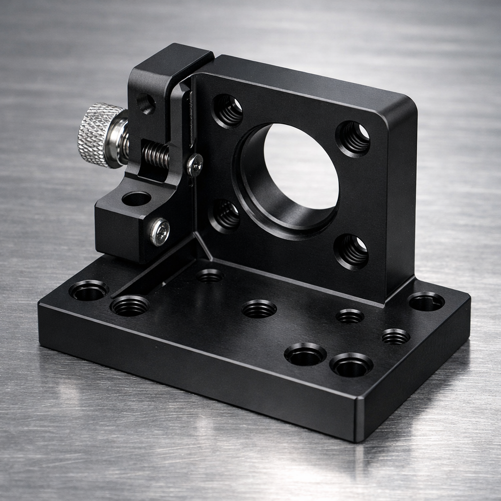
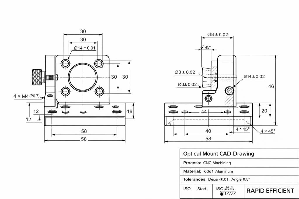
A high-precision instrumentation client required custom optical mounts with demanding specifications:
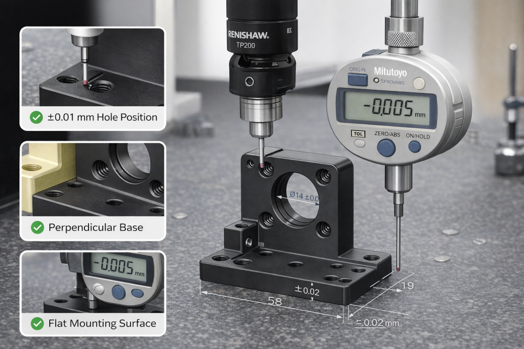
- Hole position tolerance within ±0.01 mm
- Surface flatness ≤ 0.02 mm
- Stable optical axis alignment
- Matte black anodized cosmetic finish
- Repeatable assembly performance
👉 We delivered a full batch with 100% dimensional pass rate, eliminating alignment drift during final assembly.
Customer Challenge: The Cost of Mechanical Drift
The previous supplier created recurring issues:
- Hole pattern deviation caused beam clipping at long distance
- Uneven base surfaces introduced tilt
- Critical fits changed after anodizing
- Manual calibration time increased significantly
👉 In precision optics:
Mechanical error becomes optical error.
A 0.01 mm shift at the mount can create major misalignment in the final optical path.
Why Precision Matters in Optical Mounts
Optical hardware must maintain:
- Perpendicularity between base and optical axis
- Flat contact surfaces
- Repeatable hole positioning
- Stable performance after finishing
If any of these fail:
- Beam path shifts
- Focus accuracy drops
- Calibration time increases
- End-product reliability decreases
Our Engineering Solution: Precision by Design
1. Single-Setup Machining (Datum Integrity)
Critical surfaces and hole patterns were machined in one setup to eliminate datum shift.
By finishing all critical features together, we ensured the optical axis remained perpendicular to the mounting base — essential for long-range laser alignment and repeatable assembly.
2. Fine Surface & Vibration Control
Using low-vibration finishing passes and optimized tooling paths, we achieved contact surfaces beyond standard commercial quality.
This provided a stable mechanical foundation for sensors, lenses, and optical assemblies.
3. Controlled Anodizing & Thickness Compensation
Black anodizing adds measurable thickness that can affect micron-level fits.
To maintain ±0.01 mm tolerances after finishing, we applied anodizing thickness compensation during CNC preparation.
Critical fit areas were masked when required, eliminating the need for post-finish reaming or rework.
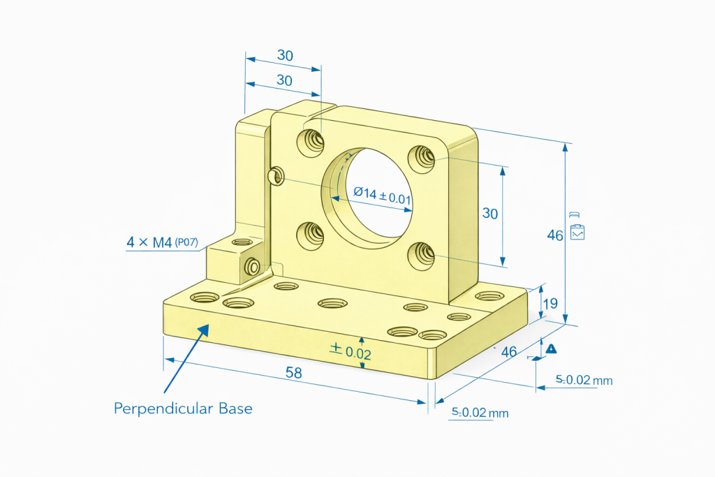
📊 Key Production Results: From Tolerance to Performance
| Feature | Requirement | Result | Why It Matters |
|---|---|---|---|
| Hole Position | ±0.01 mm | Passed | Prevents beam clipping |
| Flatness | ≤0.02 mm | Passed | Eliminates tilt & drift |
| Surface Finish | Ra 0.8–1.6 μm | Passed | Stable mounting contact |
| Cosmetic Finish | Matte Black | Passed | Reduces stray reflections |
Engineer’s Note
For optical components, dimensional repeatability matters more than appearance.
However, premium optical products usually require both.
That is why fixture stability, datum strategy, and finishing control are just as important as spindle accuracy.
Materials & High-Stability Options
For most custom optical mounts, 6061-T6 aluminum offers the best balance of:
- Weight reduction
- Machinability
- Excellent anodizing quality
For advanced applications, we also machine:
- 7075-T6 Aluminum → higher rigidity for load-bearing mounts
- Stainless Steel → maximum stability in harsh environments
- Brass → specialty alignment components
👉 See also:
Best Aluminum for CNC Machining
Related Precision Applications
Our high-precision CNC machining is also used for:
👉 CNC motor housing machining case study
👉 CNC aluminum heat sink machining case study
Need Custom Optical Hardware?
Whether you are building:
- Laboratory prototypes
- Laser systems
- Semiconductor inspection devices
- Production optical instruments
👉 Upload your CAD drawing for a DFM review on alignment tolerance, machining feasibility, and finishing risks.
FAQ
What tolerance is typical for optical mounts?
Many precision mounts require ±0.01 mm to ±0.02 mm depending on optical sensitivity.
Which material is best for optical mounts?
6061-T6 aluminum is common due to weight, machinability, and anodizing quality.
Can black anodizing affect tolerance?
Yes. Surface coating thickness must be compensated or masked in precision fit areas.