Quick Answer
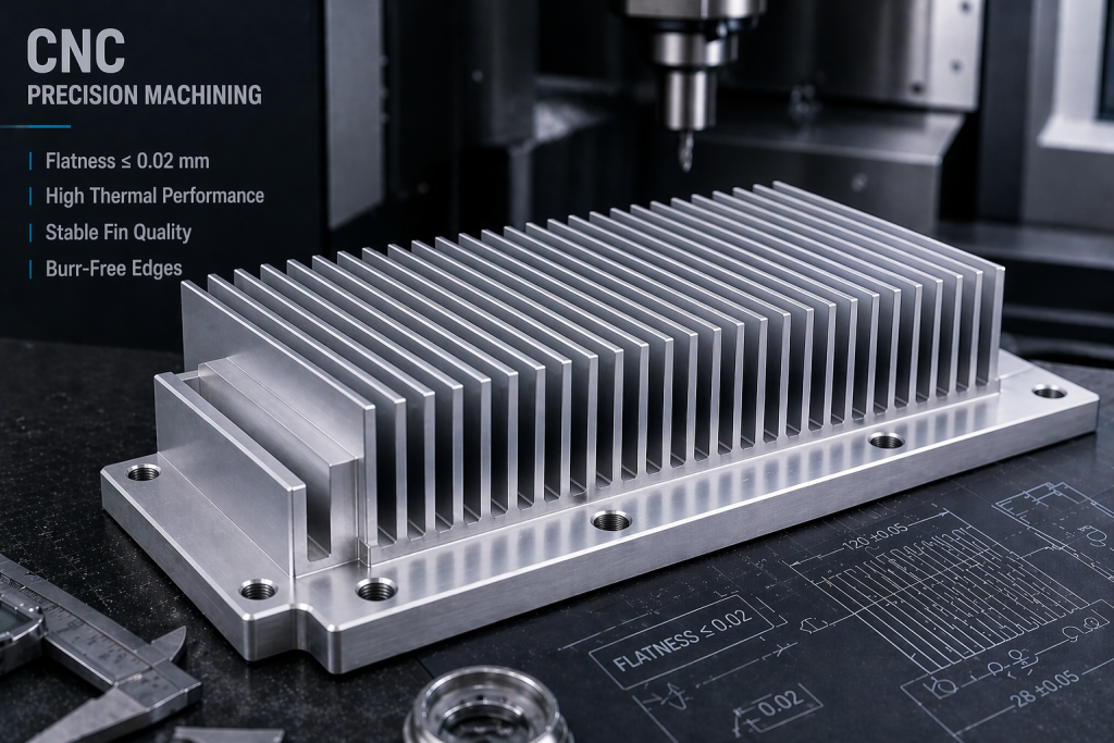
RapidEfficient machined 6061-T6 aluminum heat sinks with thin fins, a flatness-controlled mounting base, machined airflow channels, and a black anodized finish. The drawing applied a 0.02 mm flatness requirement to the defined mounting area. We separated main stock removal, fin finishing, base finishing, deburring, surface-treatment preparation, and final inspection so that clamping force, heat, trapped chips, and finishing did not undermine the functional thermal interface.
Project Overview
| Project Item | Requirement |
|---|---|
| Component | CNC-machined aluminum heat sinks |
| Material | 6061-T6 aluminum |
| Application | Power-electronics thermal assembly |
| Critical surface | Heat-source mounting area |
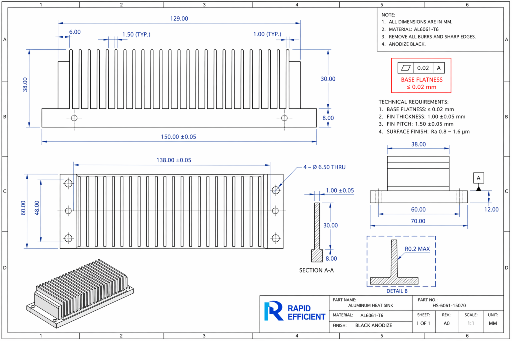
| Flatness requirement | 0.02 mm on the defined mounting area |
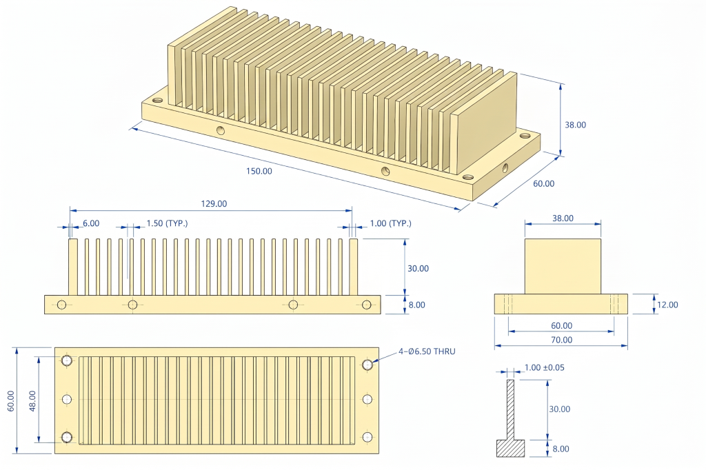
| Main geometry | Thin fins, narrow airflow channels and mounting features |
| Surface finish | Black anodized exterior |
| Main manufacturing risks | Base distortion, fin vibration, trapped chips, burrs and coating interference |
| Production focus | Stable support, staged machining and inspection after unclamping |
To protect customer confidentiality, identifying information and selected drawing dimensions are not disclosed.

Why the Mounting Base and Fins Could Not Be Controlled Separately
The mounting base formed part of the thermal path between the heat-generating component and the heat sink.
A flatness requirement of 0.02 mm means that the controlled surface must fit between two parallel planes separated by 0.02 mm. It is not a plus-or-minus size tolerance, and it does not define surface roughness.
Flatness also does not prove thermal performance by itself.
The final interface still depends on:
- The defined contact area
- Thermal-interface material
- Contact pressure
- Fastener arrangement
- Surface roughness
- Coating condition
- Heat-source geometry
- Assembly cleanliness
At the same time, the fin structure created a different manufacturing problem. Thin fins can vibrate, bend or develop burrs when tool engagement, chip evacuation or finishing direction is unstable.
The fins, base, airflow channels and mounting features therefore had to be treated as one manufacturing system.

For the broader relationship between the thermal interface, base and fin structure, see our CNC heat sink machining guide.
DFM Review Before Machining
Before finalizing the machining route, we reviewed the drawing around the features that could affect both manufacturing and assembly.
| DFM Question | Manufacturing Risk | Required Decision |
|---|---|---|
| Which area carries the flatness requirement? | Inspecting the entire base may not match the functional interface | Define the controlled mounting area |
| Is acceptance required before or after anodizing? | Coating and masking can change the final inspection condition | State the final acceptance stage |
| Which surfaces must remain uncoated? | Coating on a thermal, electrical or fitted interface may affect assembly | Mark masking areas on the drawing |
| How thin and tall are the fins? | Unsupported fins may vibrate or bend | Review tool access, engagement and finishing allowance |
| Can chips escape from the channels? | Packed chips can scratch fins or be recut | Provide a clear evacuation route |
| How will the part be supported? | Excessive clamping can temporarily force the base flat | Use broad support and controlled clamping |
| Which edges require burr control? | Aggressive deburring may alter thin fins | Define acceptable edge condition |
| How will flatness be verified? | A restrained or unsuitable measurement can give a misleading result | Agree on free-state inspection and reporting method |
This review kept the process focused on the functional interface rather than applying tight control to every surface.
Machining Route for the Aluminum Heat Sink
We Established a Stable Manufacturing Reference
The process began by establishing a repeatable reference for the base, mounting features and fin structure.
The fixture had to locate the part without forcing the mounting surface into a temporary shape. Broad support and controlled hold-down force were more important than simply tightening the part as firmly as possible.
A base that appears flat only while clamped has not demonstrated its released condition.
We Removed the Main Stock Before Final Base Finishing
The main material removal was completed before the final mounting surface was accepted.
This reduced the risk that later fin and channel machining would release stress, add heat or change the base after it had already been finished.
The machining sequence therefore separated:
- Initial reference preparation
- Main stock removal
- Fin and channel machining
- Base finishing
- Deburring and cleaning
- Surface-treatment preparation
- Final inspection
The exact cutting parameters depended on the tool, machine, stock condition, fin geometry and feature access, so they were not treated as universal values.
We Controlled Fin Engagement and Tool Exit
Thin fins required lower and more consistent cutting loads than the solid base.
Abrupt tool engagement can excite vibration, while an unsuitable exit direction can leave feather burrs along the fin edges. Excessive tool projection can also reduce stiffness and increase chatter risk.
The finishing strategy therefore considered:
- Tool reach and rigidity
- Radial and axial engagement
- Remaining finishing allowance
- Cutting direction
- Cutter exit location
- Fin support
- Tool condition
- Channel depth
- Chip-clearance space
Where fin flexibility required additional control, we reduced the unsupported height progressively instead of exposing the full fin height in one aggressive cut. The exact sequence depended on fin height, thickness, spacing, tool reach, cutting direction, and the remaining support around the feature.
The objective was not merely to make the fins look clean. It was to protect their geometry and keep the airflow channels unobstructed.
We Kept Chips Out of the Fin Channels
Narrow channels can trap aluminum chips, especially when the cutter repeatedly passes through the same confined space.
Recutting trapped chips may scratch the channel walls, damage fin edges, increase tool load and create random burrs.
The process used controlled chip-clearing moves and suitable coolant or air delivery where permitted by the machine and safety procedure. The finishing toolpath therefore had to protect the fins while giving chips a clear exit from the channels.

For broader troubleshooting of burrs, chatter, built-up edge and chip recutting, review our guide to common aluminum machining problems.
We Finished the Mounting Base After the Main Stock Removal
The critical mounting area received its finishing operation after the main structural machining stages.
Support and hold-down force were kept controlled so that the surface was not machined while artificially distorted. The base condition was then reviewed after the part was released from the fixture.
This sequencing helped separate real surface geometry from temporary clamping deformation.
We Deburred Without Thinning the Fins
Heat-sink deburring requires more control than general edge breaking.
Aggressive abrasive blending can:
- Reduce fin thickness
- Round functional edges
- Damage the mounting surface
- Create inconsistent cosmetic texture
- Leave abrasive contamination in narrow channels
Deburring therefore focused on the actual burr locations, followed by cleaning and inspection of the airflow channels.
Preparing the Heat Sink for Black Anodizing
Anodizing does not repair machining marks, scratches, burrs or an out-of-flat base. In many cases, it makes inconsistent preparation easier to see.
Before finishing, we reviewed:
- Fin-edge condition
- Channel cleanliness
- Cosmetic surfaces
- Mounting-face requirements
- Thread and hole protection
- Electrical-contact areas
- Rack-mark location
- Masking boundaries
- Post-finish inspection features
The black anodized exterior was coordinated with the drawing rather than treated as a general instruction to coat every exposed surface.
Thermal-contact faces, fitted features, threads or grounding areas may require masking when the drawing and assembly function demand it. The required areas must be identified before finishing, not decided after the parts return from the anodizing supplier.
For the coating and masking boundary, see our comparison of anodizing and powder coating for aluminum parts.
Inspection Had to Match the Heat-Sink Feature
Different features required different inspection approaches.
| Feature | Main Risk | Practical Verification | Inspection State |
|---|---|---|---|
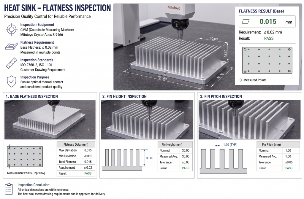
| Mounting-base flatness | Clamping distortion or incomplete measurement area | Surface-plate indicator sweep for process control; CMM or another approved method for recorded acceptance | After unclamping and in the drawing-defined finish state |
| Mounting-face roughness | Unsuitable thermal-interface surface | Profilometer when roughness is specified | Before or after finishing as defined |
| Fin thickness and spacing | Contact pressure bending the fins | Suitable optical, vision or low-force dimensional method | Before surface treatment |
| Fin-edge condition | Burrs inside airflow channels | Visual and magnified inspection | After deburring and cleaning |
| Mounting holes and threads | Coating buildup or masking errors | Pin gauges, thread gauges or approved dimensional inspection | After finishing where required |
| Anodized appearance | Color, rack, handling or preparation variation | Defined lighting and approved appearance criteria | After surface treatment |
| Thermal performance | Assembly-dependent behavior | Customer system or thermal validation | After final assembly |

Flatness inspection was performed in the released condition. The inspection method had to cover the defined mounting area with enough information to support the drawing requirement.
A few isolated points or a measurement taken while the part remained clamped could not establish the final base condition.
For repeat-production projects, the inspection scope, sample frequency and required evidence should be agreed before manufacturing. Our first article inspection guide explains what buyers should define before approving production.
Project Outcome
The heat sinks were completed using a controlled sequence that separated main stock removal, fin finishing, base finishing, deburring, anodizing preparation and post-finish inspection.

The specified mounting-base flatness and other drawing requirements were checked in the agreed acceptance condition before the parts were released for delivery.
Dimensional acceptance of the machined heat sink did not replace system-level thermal validation. The completed assembly still depended on the heat source, thermal-interface material, mounting pressure, airflow and operating conditions defined by the customer.
When This Machining Route Is Appropriate
This route is suitable when a heat sink requires custom features that cannot be obtained efficiently from a standard profile, such as:
- A defined component-mounting interface
- Precision hole patterns
- Integrated pockets
- Custom fin interruptions
- Connector or sensor features
- Threaded mounting points
- Multi-side machining
- Controlled cosmetic surfaces
- Prototype or low-volume production
CNC machining is not automatically the best route for every heat sink.
For high-volume parts or very dense fin structures, an extrusion, skived-fin design, bonded-fin assembly, die casting, heat pipe, vapor chamber or liquid cold plate may provide a better combination of thermal performance and manufacturing cost.
Buyer Checklist for CNC-Machined Heat Sinks
Before requesting a quotation, provide:
- STEP model and controlled 2D drawing
- Aluminum alloy and temper
- Starting-stock requirements if already defined
- Heat-source location and contact area
- Base flatness requirement and controlled area
- Surface-roughness requirement where functional
- Thermal-interface material
- Fastener arrangement and mounting pressure
- Fin thickness, height and spacing
- Airflow direction and blocked-channel restrictions
- Threads, holes and fitted features
- Anodizing type, color and cosmetic surfaces
- Masking and rack-mark locations
- Acceptance state before or after finishing
- Inspection and reporting requirements
- Prototype and expected repeat quantity
Review Your CNC Heat Sink Project
For a useful DFM review, send the STEP model, 2D drawing, quantity, aluminum grade and temper, heat-source contact area, flatness requirement, fin geometry, thermal-interface information, anodizing and masking requirements, and required inspection evidence.
RapidEfficient can review the machining sequence, thin-fin risks, base support, burr-control strategy, surface-treatment boundary and inspection plan before quotation.
Review our CNC aluminum machining services or send the drawings and project requirements for project evaluation.