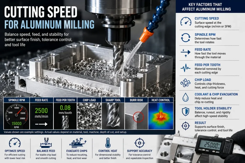
Cutting speed is one of the first numbers people ask about when milling aluminum.
But in real CNC work, cutting speed alone does not decide whether the part machines well.
A good aluminum milling result depends on the balance between:
- cutting speed
- spindle RPM
- feed rate
- chip load
- cutter diameter
- flute count
- tool coating or polish
- chip evacuation
- coolant or air blast
- part rigidity
- wall thickness
- tolerance
- surface finish requirement
This is why one aluminum part can run clean at high speed, while another part with the same material may show burrs, chatter, tool marks, or unstable dimensions.
The better question is not only:
What cutting speed should I use for aluminum?
The better question is:
What cutting speed, RPM, feed, chip load, tool geometry, and setup condition can remove chips cleanly without creating heat, burrs, chatter, or dimensional drift?
The Simple Answer: What Is Cutting Speed in Aluminum Milling?
Cutting speed is the surface speed between the cutting edge and the aluminum workpiece.
It is usually expressed as:
| Unit | Meaning |
|---|---|
| m/min | meters per minute |
| SFM | surface feet per minute |
Cutting speed is not the same as spindle RPM.
RPM is how fast the tool rotates. Cutting speed depends on both RPM and cutter diameter.
A larger cutter reaches a higher surface speed at the same RPM. A smaller cutter needs higher RPM to reach the same surface speed.
For aluminum milling, cutting speed must be selected together with feed per tooth, flute count, depth of cut, coolant strategy, and chip evacuation.
If the speed is too low, aluminum may rub instead of cutting cleanly. If the speed is too high for the setup, the tool may overheat, chips may weld to the edge, and surface finish can become unstable.
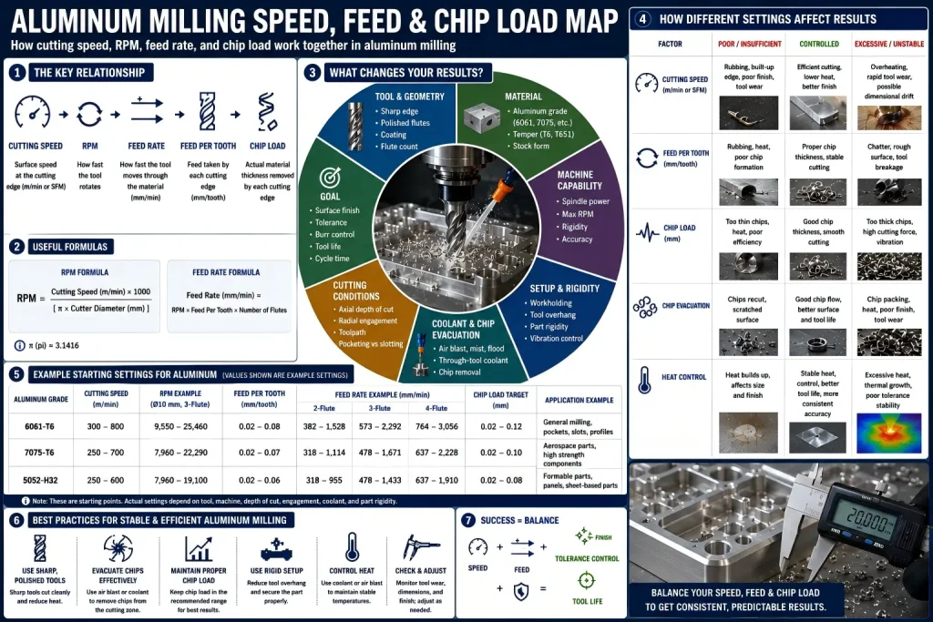
Cutting Speed, RPM, Feed Rate, and Chip Load Are Not the Same
Many aluminum milling problems happen because these terms are mixed together.
| Term | What It Means | Why It Matters |
|---|---|---|
| Cutting speed | Surface speed at the cutting edge | Affects heat, tool wear, built-up edge, and cutting efficiency |
| RPM | Tool revolutions per minute | Converts cutting speed into machine spindle speed |
| Feed rate | Machine movement per minute | Controls how fast the cutter moves through the part |
| Feed per tooth | Feed taken by each cutting edge | Affects chip thickness and cutting force |
| Chip load | Material thickness removed by each cutting edge | Helps prevent rubbing, overheating, and poor finish |
| Flute count | Number of cutting edges | Affects chip space, feed rate, and evacuation |
| Radial depth of cut | Side engagement | Affects tool load and chatter |
| Axial depth of cut | Vertical cutting depth | Affects cutting force, deflection, and heat |
A high RPM with too little feed can still produce poor results. The tool may rub the aluminum instead of cutting a proper chip.
A high feed rate with poor chip evacuation can also fail. Chips may recut the surface, damage the finish, or stick to the cutting edge.
Good aluminum milling is not about choosing the highest speed. It is about keeping chip formation stable.
Basic Cutting Speed Logic for Aluminum Milling
Aluminum is usually easier to mill than stainless steel or titanium, but it has its own problems.
The common risks are:
- built-up edge
- chip welding
- burrs
- smeared surface finish
- chatter marks
- tool wear from recutting chips
- poor hole or slot finish
- dimensional drift on thin walls
- poor cosmetic appearance after machining
A practical aluminum cutting speed strategy should consider:
| Factor | Why It Changes the Speed Decision |
|---|---|
| Aluminum grade | 6061, 7075, 2024, 5052, and cast aluminum cut differently |
| Temper | T6, T651, annealed, or soft condition affects chip behavior |
| Tool diameter | Small tools need higher RPM for the same cutting speed |
| Tool geometry | Polished flutes and sharp edges help reduce sticking |
| Flute count | 2-flute and 3-flute tools often clear chips better in aluminum |
| Coating | Some coatings help, but a polished, sharp edge is often more important |
| Coolant / air blast | Helps remove chips and reduce built-up edge |
| Slotting vs side milling | Slotting traps chips and needs more conservative planning |
| Thin wall features | Aggressive speed and feed may cause vibration or deflection |
| Surface finish | Finishing passes need stable chip load and low runout |
| Tolerance | Tight features may need process stability more than maximum speed |
For flute count, cutter geometry, coatings, tool reach, and feature-based selection, review our aluminum milling cutter selection guide.
Why Aluminum Can Still Be Difficult at High Speed
Aluminum has good machinability, but it can become difficult when heat, chip load, and chip evacuation are not controlled.
The main issue is that aluminum chips can stick to the cutting edge. This is called built-up edge.
Built-up edge changes the tool geometry during cutting. Once this happens, the tool may stop cutting cleanly. The part may show rough marks, oversized burrs, poor finish, or unstable dimensions.
High speed can help when the tool, machine, coolant, and chip evacuation are ready for it. But speed alone does not solve the problem.
| Problem | Common Cause |
|---|---|
| Burrs on exit edges | Dull tool, poor support, wrong feed, weak chip evacuation |
| Smeared surface | Built-up edge or rubbing |
| Chatter marks | Long tool overhang, weak fixture, thin wall vibration |
| Tool loading | Chips sticking in flutes |
| Poor slot finish | Chips trapped in the slot |
| Heat marks | Too much rubbing or recutting |
| Dimensional drift | Tool deflection, part movement, heat, or unstable finishing pass |
How Cutter Diameter Changes RPM
Cutting speed and RPM are linked.
For the same cutting speed:
- a small cutter needs higher RPM
- a large cutter needs lower RPM
This is why a 3 mm end mill and a 12 mm end mill should not use the same RPM just because both are cutting aluminum.
| Cutter Situation | Practical Risk |
|---|---|
| Small end mill | Needs high RPM; tool is fragile; chip load must be controlled |
| Large end mill | Lower RPM may reach the same surface speed; machine torque matters |
| Long tool overhang | Speed may need reduction to avoid chatter |
| Deep pocket tool | Chip evacuation becomes more important |
| Ball nose tool | Effective cutting diameter changes with contact point |
| Corner radius tool | Actual contact and chip thickness need review |
| Face mill | Insert geometry, balance, and spindle power matter |
At higher spindle speeds, the balance of the tool holder and tool assembly becomes more important. A small carbide end mill may need high RPM to reach the planned cutting speed, but high RPM also makes vibration, runout, and spindle condition more sensitive.
If the tool holder is not suitable for the target speed, small vibrations can affect surface finish, tool life, cutting edge stability, and dimensional repeatability. This does not mean every aluminum part needs a specially balanced holder. But for high-speed finishing, small tools, cosmetic surfaces, tight bores, or thin-wall parts, the supplier may review tool-holder balance, tool stickout, spindle condition, and runout before choosing aggressive RPM.
If the shop only raises RPM without adjusting feed per tooth, the tool may rub. If the shop raises feed without checking chip evacuation, the part may get burrs or surface damage.
Feed Per Tooth Matters More Than Many Buyers Think
Feed per tooth controls how much material each flute removes.
If feed per tooth is too low, the cutting edge may rub the aluminum surface. This can increase heat and cause built-up edge.
If feed per tooth is too high, the tool may deflect, chatter, or break, especially in small cutters, thin walls, deep slots, or weak fixtures.
| Feed Per Tooth Condition | Possible Result |
|---|---|
| Too low | Rubbing, heat, poor finish, built-up edge |
| Too high | Tool deflection, chatter, rough surface, tool breakage |
| Stable | Clean chips, better finish, controlled cutting force |
| Unstable during cornering | Chatter or gouging in internal corners |
| Not adjusted for tool length | Vibration and dimensional error |
| Not adjusted for flute count | Overfeeding or underfeeding per edge |
Feed per tooth also becomes more sensitive in internal corners. When an end mill enters a tight corner, the tool engagement angle can increase quickly. This can raise cutting force, chip thickness, and vibration risk in a small area of the tool path.
If the feed rate is not adjusted, the corner may show chatter marks, gouging, burrs, or local dimensional error. For tight internal corners, the process may need CAM toolpath review, feed reduction in corners, trochoidal or adaptive toolpaths, or a slightly larger corner radius if the design allows it.
This is a process planning issue, not only a cutting speed issue. A stable straight-line cut can still become unstable when the tool enters a tight corner.
This is why aluminum milling speed should not be reviewed without feed rate and chip load.
2-Flute vs 3-Flute Tools for Aluminum Speed Planning
Tool geometry changes the safe cutting speed and feed plan.
For many aluminum CNC parts, 2-flute and 3-flute carbide end mills are common choices.
| Tool Type | Where It Helps | Watch Out For |
|---|---|---|
| 2-flute end mill | Slotting, chip evacuation, small tools, softer aluminum | Lower feed capacity than more flutes |
| 3-flute end mill | Balanced speed, finish, productivity, general aluminum milling | Needs good chip evacuation |
| Single-flute tool | Plastics or very small tools in some cases | Not a default for all aluminum parts |
| 4-flute tool | Can work in some finishing or rigid setups | May pack chips in aluminum if flute space is limited |
| Polished flute tool | Helps reduce sticking and built-up edge | Still needs correct chip load |
| Coated tool | May help in selected cases | Coating cannot fix poor chip evacuation |
The best tool depends on the part. A thin-wall housing, a deep slot, a cosmetic face, and a high-volume plate job may need different speed and feed choices.
Cutting Speed for 6061 vs 7075 Aluminum
6061 and 7075 aluminum are both common CNC materials, but they do not behave exactly the same.
| Material | Milling Behavior | Speed Planning Note |
|---|---|---|
| 6061-T6 | Good general machinability, common for prototypes and production | Often forgiving, but can still smear with dull tools |
| 6061-T651 | More stable plate condition than some stock forms | Useful when flatness and stability matter |
| 7075-T6 | Stronger and harder than 6061 | Can cut cleanly, but tool wear and stress need review |
| 7075-T651 | Often used for stronger machined components | Good for strength-driven parts, not automatically better for every tolerance |
| 5052 | Better for sheet forming than heavy CNC milling | Softer behavior may create burrs or poor chip control |
| Cast aluminum | Depends strongly on silicon content and casting quality | Abrasive particles and porosity can affect tool life |
If the article question is mainly about material choice, see our 6061 vs 7075 aluminum CNC machining guide.
This article is focused on cutting speed and machining behavior, not general material selection.
Slotting, Pocketing, and Finishing Need Different Speed Decisions
The same aluminum part may need different cutting conditions in different features.
| Operation | Speed and Feed Risk |
|---|---|
| Full slotting | Chips are trapped; heat and recutting risk increase |
| Adaptive clearing | More stable engagement can allow higher productivity |
| Side milling | Radial engagement changes tool load |
| Finishing pass | Surface finish and tool runout become more important |
| Deep pocket milling | Chip evacuation and tool overhang are critical |
| Thin wall milling | Cutting force can bend the wall |
| Thread milling | Tool path and chip evacuation affect thread quality |
| Face milling | Insert geometry, runout, and surface speed affect finish |
| Small hole interpolation | Tool stiffness and chip load matter |
| Cosmetic surface milling | Stable final pass is more important than maximum speed |
For side milling and finishing direction choices, see our Climb Milling vs Conventional Milling guide.
Coolant, Air Blast, and Chip Evacuation
Aluminum milling often benefits from strong chip evacuation.
The exact method depends on machine setup, part geometry, tolerance, and finish requirement.
| Method | Where It Helps | Risk |
|---|---|---|
| Air blast | Clears chips from open pockets and slots | May not control heat enough in all cases |
| Mist coolant | Helps lubrication and chip control | Requires stable machine setup |
| Flood coolant | Helps cooling and chip removal | Can still fail if chips are trapped |
| Through-tool coolant | Useful for deeper features when available | Depends on tool and machine capability |
| Dry cutting | Possible in some setups | Built-up edge risk must be reviewed |
Chips should leave the cutting zone quickly. If chips stay in the pocket or slot, the tool may recut them. Recut chips can scratch the surface, wear the tool, and create burrs.
For more on wear patterns and troubleshooting, see our CNC tool wear guide.
Cutting Speed and Surface Finish
A higher cutting speed does not always create a better surface finish.
Surface finish depends on:
- tool sharpness
- tool runout
- feed per tooth
- cutter path
- chip evacuation
- finishing allowance
- fixture stability
- wall rigidity
- coolant condition
- tool wear
- final inspection method
For cosmetic aluminum parts, the finishing pass should be planned separately from roughing.
A roughing pass can focus on material removal. A finishing pass should focus on stable engagement, clean chip flow, low vibration, and controlled tool marks.
If the part will later be anodized, bead blasted, plated, or polished, the machining marks before finishing can still matter.
For finish planning, see our CNC surface finishes guide.
Cutting Speed and Tolerance Stability
Cutting speed can affect tolerance indirectly.
It may change:
- heat in the cutting zone
- tool wear rate
- built-up edge
- cutting force
- tool deflection
- part vibration
- final surface condition
- burr size
- inspection repeatability
A tight aluminum tolerance is not achieved by speed alone. It also depends on stock condition, tool path, roughing and finishing sequence, fixture design, temperature, and inspection method.
This is especially important for:
| Feature | Why Speed Planning Matters |
|---|---|
| Thin walls | Heat and cutting force can move the wall |
| Long flat surfaces | Residual stress and clamping can affect flatness |
| Precision bores | Tool deflection and finish pass stability matter |
| Bearing seats | Surface finish and size must be controlled together |
| Threaded holes | Burrs and chip control affect gauge fit |
| Cosmetic faces | Tool marks may remain visible after finishing |
| Press-fit areas | Coating or anodizing may change final size |
Aluminum expands noticeably with heat. During high-speed milling, friction, tool wear, chip recutting, or unstable cooling can transfer heat into the workpiece. If a tight feature is measured while the part is still warm, the size may look acceptable during machining but change after the part cools.
This matters for thin walls, precision bores, bearing seats, long flat surfaces, and tight-fit features. For tolerance-sensitive aluminum parts, the supplier may review stable cooling, roughing and finishing sequence, part relaxation time, and final inspection temperature. The goal is not only to cut fast, but to measure the final part under a condition that matches the drawing requirement.
For dimensional planning, see our CNC machining tolerances guide.
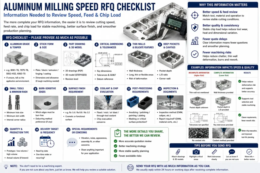
Buyer RFQ Checks Before Aluminum Milling
Buyers do not need to provide the final cutting speed. That is usually the supplier’s process responsibility.
But buyers should provide the information that affects speed, feed, tooling, and inspection decisions.
| RFQ Check | What to Provide |
|---|---|
| Aluminum grade | 6061, 7075, 5052, 2024, cast aluminum, or other |
| Temper / stock form | T6, T651, plate, extrusion, bar, casting |
| Critical dimensions | Mark features that truly need tight control |
| Surface finish | Ra value, cosmetic surface, tool mark limit, or post-finish |
| Thin walls | Wall thickness and unsupported height |
| Deep pockets | Pocket depth, corner radius, and chip evacuation risk |
| Small tools | Minimum radius, small slots, micro features |
| Burr control | Edges, holes, slots, threads, and cosmetic boundaries |
| Post-processing | Anodizing, bead blasting, plating, polishing, or painting |
| Inspection requirement | CMM, thread gauge, surface roughness report, or visual standard |
| Quantity | Prototype, low volume, or repeat production |
| Delivery target | Helps balance speed, risk, and inspection plan |
The goal is not to tell the CNC shop exactly what cutting speed to use. The goal is to give enough information so the shop can choose a stable process instead of guessing.
Practical Drawing Notes for Aluminum Milling
Example 1: Cosmetic Aluminum Face
Visible face requires controlled tool marks. Final finishing pass required. Supplier to review cutter path and surface finish before production.
This note helps prevent roughing marks from being left on the cosmetic surface.
Example 2: Thin-Wall Aluminum Housing
Thin wall area shown in red. Supplier to review machining sequence, tool engagement, and inspection after stress-relief or final finishing if required.
This helps reduce deformation and tolerance drift.
Example 3: Burr-Sensitive Slot
Slot edges must be free from loose burrs. Deburring method must not round functional edge beyond drawing requirement.
This links speed and chip control to final edge quality.
Example 4: Tight Bore After Milling
Bore diameter applies after final machining. Check with suitable gauge or inspection method. Burrs at entry and exit edges must be removed.
This prevents cutting speed decisions from ignoring final inspection.
Example 5: Anodized Aluminum Part
Dimensions marked as critical apply after machining and before anodizing unless otherwise stated. Supplier to review coating allowance for tight-fit areas.
This avoids confusion when machining tolerance and finishing thickness interact.
Common Mistakes When Setting Aluminum Milling Speed
Mistake 1: Using the Same RPM for Every Tool
A small end mill and a large end mill should not use the same RPM simply because both cut aluminum.
Mistake 2: Increasing RPM Without Increasing Feed Correctly
If RPM rises but feed per tooth becomes too low, the tool may rub instead of cut.
Mistake 3: Ignoring Chip Evacuation
Aluminum chips can stick, recut, and scratch the part. Chip evacuation is often as important as speed.
Mistake 4: Using Too Many Flutes in Deep Slots
More flutes can reduce chip space. In aluminum slotting, this can cause chip packing and tool loading.
Mistake 5: Treating Roughing and Finishing the Same
Roughing and finishing usually need different priorities. Roughing removes material. Finishing controls surface quality and final dimensions.
Mistake 6: Chasing Maximum Speed on Weak Parts
Thin walls, long tool overhang, weak clamping, and deep pockets may need a more conservative process.
Rapid Efficient Support for Aluminum Milling Review
Rapid Efficient can review aluminum CNC parts that require stable milling speed, good surface finish, burr control, tight tolerance, thin-wall stability, or post-finish planning.
We do not need the buyer to provide final machine parameters. Instead, we review the drawing, material, part geometry, finish requirement, quantity, and inspection needs before quotation.
Send us your STEP file, 2D drawing, aluminum grade, surface finish requirement, critical dimensions, quantity, and post-processing needs.
For aluminum CNC projects, see our CNC aluminum machining services and CNC machining design guide.
Buyer Questions About Aluminum Milling Speed
What is the best cutting speed for aluminum milling?
There is no single best cutting speed for all aluminum parts. It depends on aluminum grade, cutter diameter, flute count, tool geometry, machine RPM, chip load, coolant, fixture rigidity, and part features.
Is higher RPM always better for aluminum?
No. Higher RPM can help in the right setup, but it can also cause rubbing, heat, tool loading, chatter, or poor finish if feed and chip evacuation are not controlled.
Why does aluminum stick to the cutter?
Aluminum can form built-up edge when heat, chip load, tool sharpness, coating, or chip evacuation is not controlled. This changes the cutting edge and can damage surface finish.
Should aluminum milling use 2-flute or 3-flute tools?
Both can work. 2-flute tools help with chip evacuation, especially in slots and smaller tools. 3-flute tools often give a good balance of speed, finish, and productivity in many aluminum milling jobs.
Does cutting speed affect burrs?
Yes, but indirectly. Burrs are affected by tool sharpness, feed, speed, chip evacuation, exit direction, support, tool wear, and material condition.
Should buyers specify cutting speed on drawings?
Usually no. Buyers should specify material, tolerance, surface finish, burr limits, post-processing, and inspection needs. The supplier should choose the cutting speed and feed strategy based on the actual process.