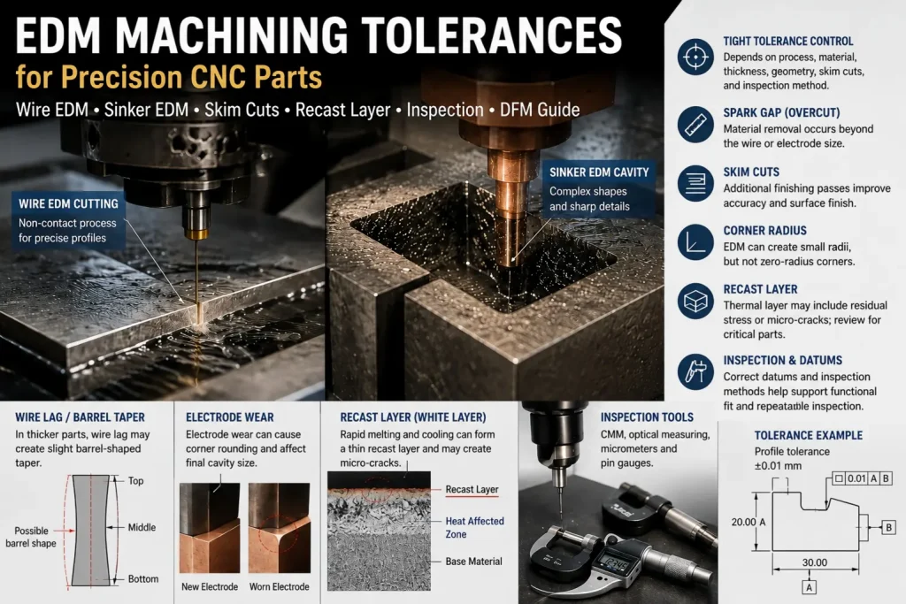
EDM can hold very tight tolerances on selected features, but EDM tolerance is not a fixed number that applies to every part.
Wire EDM, sinker EDM, and EDM drilling all remove material by electrical discharge instead of mechanical cutting. This makes EDM useful for hard metals, sharp internal features, thin sections, deep cavities, small holes, tool steel, stainless steel, titanium, carbide, and complex profiles that may be difficult to machine with milling or turning.
For buyers, the important question is not only:
How tight can EDM machining tolerance be?
The better question is:
Which feature needs tight EDM tolerance, and do the material, thickness, geometry, surface finish, recast layer, and inspection method support that requirement?
EDM Tolerance Is Not One Fixed Capability
EDM machining tolerance depends on the EDM process, part geometry, material, thickness, machine condition, electrode or wire size, skim cuts, flushing, fixture stability, surface finish, and inspection method.
A simple thin profile may be easier to control than a tall thick part with taper risk. A straight external profile may be easier than a deep cavity, narrow slot, small internal corner, or feature close to a thin wall.
For many precision parts, EDM is used because it can avoid cutting force and tool deflection. But EDM still has its own tolerance risks, including spark gap, wire path compensation, electrode wear, flushing limits, thermal effects, and recast layer.
Use EDM when the feature needs its process advantages. Do not use EDM only because the drawing says a very tight tolerance.
What EDM Machining Means
EDM stands for electrical discharge machining. It removes material with controlled electrical sparks between an electrode and a conductive workpiece.
There are several common EDM processes:
| EDM Type | Typical Use | Buyer Check |
|---|---|---|
| Wire EDM | Cutting profiles, slots, punches, dies, plates, thin walls, complex outlines | Needs conductive material, wire access, corner radius review, and cut path planning |
| Sinker EDM | Blind cavities, mold details, ribs, pockets, sharp corners, complex forms | Needs electrode design, electrode wear control, and surface finish review |
| EDM drilling | Small deep holes, start holes for wire EDM, cooling holes, hard material holes | Needs hole size, depth, straightness, burr/recast review, and flushing control |
| Micro EDM | Very small precision features | Needs special review for geometry, inspection, and handling |
| EDM + CNC milling | Hybrid route for complex parts | Needs process order, datum control, and final inspection plan |
For service capability, conductive-metal profiles, slots, and cutouts can also be reviewed through our wire cutting service page.
EDM is usually used on electrically conductive materials. It is not the right process for ordinary plastics, ceramics, or non-conductive materials unless a special process route is reviewed.
When EDM Is Better Than CNC Milling
EDM can be better than CNC milling when the feature is difficult to cut with a rotating tool.
Common examples include:
| Part Feature | Why EDM May Help |
|---|---|
| Sharp internal corners | Milling cutters leave a radius, while EDM can create much smaller corner details |
| Hard tool steel | EDM can cut hardened material without heavy cutting forces |
| Thin ribs or walls | Non-contact cutting reduces mechanical deflection risk |
| Deep narrow slots | Milling tools may chatter, deflect, or break |
| Small complex profiles | Wire EDM can follow detailed 2D profiles accurately |
| Mold cavities | Sinker EDM can form shapes that are difficult to mill directly |
| Carbide or superalloy parts | EDM can cut hard conductive materials that are difficult for conventional tools |
| Parts after heat treatment | EDM can reduce post-heat-treatment machining stress in selected features |
EDM is not always the fastest or cheapest method. For simple pockets, open surfaces, large material removal, and standard holes, CNC milling may be faster and more economical.
Use EDM when the feature needs tight profile control, low cutting force, small inside radii, hard-material cutting, or geometry that would be risky for milling.
When CNC Milling May Be Better Than EDM
CNC milling is often better when the part has open access, standard radii, simple holes, broad surfaces, or high material removal volume.
EDM is slower than milling for many simple features. It may also add costs for programming, electrode manufacturing, skim cuts, surface finish control, recast-layer review, and inspection.
| Situation | Milling May Be Better |
|---|---|
| Open pocket with normal corner radius | Standard end mills can machine it efficiently |
| Large flat surface | Milling is usually faster |
| Non-conductive material | EDM is usually not suitable |
| Loose general tolerance | EDM may be unnecessary |
| High-volume simple part | Milling, turning, stamping, or laser cutting may be more economical |
| Surface must avoid recast layer | Milling or grinding may be preferred |
| Feature can accept tool radius | EDM may not add value |
| Fast prototype with simple geometry | CNC milling may reduce lead time |
The best process is not the one with the tightest possible tolerance. The best process is the one that fits the feature, material, tolerance, cost, and inspection requirement.
What Controls EDM Machining Tolerances
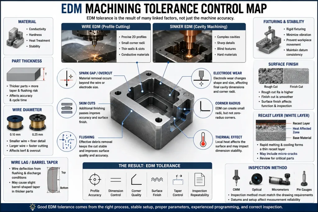
EDM tolerance is controlled by several linked factors.
| Factor | How It Affects EDM Tolerance |
|---|---|
| EDM type | Wire EDM, sinker EDM, and EDM drilling have different tolerance behavior |
| Material conductivity | Stable discharge depends on material behavior |
| Material thickness | Thick parts may increase taper, flushing difficulty, and cycle time |
| Wire diameter | Smaller wire may allow finer features but can affect speed and stability |
| Spark gap / overcut | EDM removes material beyond the physical wire or electrode size |
| Skim cuts | Extra finishing passes can improve accuracy and surface finish |
| Flushing | Poor debris removal can affect cut stability and surface quality |
| Electrode wear | Sinker EDM accuracy depends on electrode shape and wear control |
| Fixturing | Workpiece movement, stress relief, or poor support can change final size |
| Surface finish | Rough cuts and finish cuts create different surface conditions |
| Recast layer | Thermal material change may need review for critical parts |
| Inspection method | CMM, optical inspection, gauges, or profilometer results must match the drawing |
EDM tolerance is controlled by the full process chain, not only by the EDM machine accuracy.
Wire EDM Tolerance: What Buyers Should Know
Wire EDM is often used for accurate 2D profiles, slots, punches, dies, plates, and hard-metal features.
The wire does not touch the workpiece like a cutter. Sparks jump across a small gap, melting and removing material. Because the wire and spark gap both affect the cut, the final size depends on wire path compensation and process control.
Important buyer checks include:
| Wire EDM Check | Why It Matters |
|---|---|
| Material must be conductive | Wire EDM needs electrical discharge through the workpiece |
| Part thickness | Thick parts can increase taper or flushing risk |
| Profile tolerance | Defines how tightly the cut path must be controlled |
| Corner radius | The smallest internal radius depends on wire size and spark gap |
| Start hole | Internal cutouts need a start hole unless geometry allows entry |
| Skim cuts | Extra passes may improve accuracy and finish |
| Taper allowance | Tall parts may need taper control or extra inspection |
| Tab or cut-off area | Small attachment points may need removal or finishing |
| Surface finish | Rough cut and finish cut surfaces are different |
| Recast layer | Critical fatigue, sealing, or corrosion areas may need review |
One geometry concern on thicker or taller wire EDM parts is wire lag. During cutting, the wire can deflect slightly because of flushing pressure, discharge conditions, and microscopic debris in the cut channel. This may create a small taper or barrel-shaped difference between the top, middle, and bottom of the cut face.
This does not mean thick wire EDM parts cannot hold tight tolerances. It means the supplier should review part thickness, profile tolerance, flushing, cutting speed, skim cuts, and wire path compensation before confirming the final tolerance.
For tight linear profiles, tooling inserts, thick plates, or tall cut sections, buyers may ask the supplier whether taper control or top-and-bottom profile inspection is needed.
If a buyer asks for very tight tolerance on a thick part, the supplier should review taper, flushing, wire path, skim cuts, and inspection method before confirming the quote.
Sinker EDM Tolerance: What Buyers Should Know
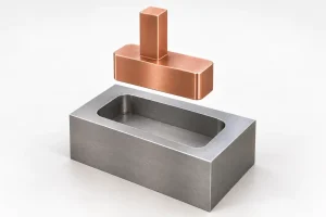
Sinker EDM uses a shaped electrode to burn a cavity or feature into the workpiece. It is common for mold details, blind cavities, ribs, narrow slots, and complex forms that are hard to mill.
Sinker EDM tolerance depends strongly on electrode design and electrode wear.
| Sinker EDM Check | Why It Matters |
|---|---|
| Electrode material | Graphite, copper, or other electrode materials behave differently |
| Electrode wear | Wear can change cavity size and shape |
| Cavity depth | Deep cavities are harder to flush and inspect |
| Corner detail | EDM can create small radii, but not zero-radius corners |
| Surface finish | Fine finish may need finishing burns or polishing |
| Draft or taper | Some cavities may need sidewall review |
| Datum setup | Electrode position must match the drawing datum structure |
| Multiple electrodes | Roughing and finishing electrodes may be needed |
| Inspection access | Deep or narrow cavities may be difficult to measure |
| Recast layer | Critical surfaces may need post-EDM review or removal |
Electrode wear is an important factor in sinker EDM tolerance. The same electrical discharge that removes material from the workpiece can also wear the copper or graphite electrode. As the electrode wears, sharp corners and fine details may become slightly rounded.
This is why a sinker EDM cavity should not be described only as “sharp corner” or “no radius.” If the corner is functional, the drawing should define the maximum acceptable corner radius or the mating-part clearance requirement.
For fine cavity details, the supplier may need separate roughing and finishing electrodes. This adds cost and lead time, but it can help control size, corner detail, and final surface condition more consistently.
Sinker EDM is powerful, but it is not simply “more accurate milling.” It is a different process with different tolerance drivers.
For cavities and mold-like features, the drawing should define which surfaces are critical, which radii matter, and whether the final surface is as-EDM, polished, textured, or post-processed.
EDM Drilling Tolerance: Small Deep Holes Need Review
EDM drilling can create small deep holes in hard conductive materials. It is often used for start holes, cooling holes, vent holes, and features that are difficult to drill mechanically.
But small EDM holes still need tolerance review.
| EDM Hole Check | Why It Matters |
|---|---|
| Hole diameter | Small diameter tolerance depends on electrode size and wear |
| Hole depth | Deep holes increase flushing and straightness risk |
| Breakthrough condition | Exit edge may need burr/recast review |
| Hole position | CMM or optical inspection may be needed |
| Hole angle | Angled holes need setup and inspection planning |
| Surface condition | Internal surface may not match drilled or reamed finish |
| Recast layer | Critical flow or fatigue holes may need extra review |
| Cleaning | Small holes can trap debris or residue |
If the hole controls flow, cooling, sealing, fatigue strength, or assembly, the RFQ should include the hole function and inspection requirement.
Corner Radius and Spark Gap Are Common Sources of Confusion
EDM can create much smaller inside corners than standard milling, but EDM does not create a perfectly sharp internal corner.
Wire EDM internal corner size depends on wire diameter, spark gap, machine strategy, material thickness, and skim cuts. Sinker EDM corner detail depends on electrode design, wear, and discharge setting.
| Feature | Buyer Question |
|---|---|
| Internal corner | What is the minimum acceptable radius? |
| Slot width | Does wire diameter and spark gap allow the slot? |
| Thin rib | Can the rib survive handling and flushing? |
| Sharp punch profile | Is corner radius function-critical or cosmetic? |
| Mold insert corner | Is polishing or lapping required after EDM? |
| Keyway or spline | Does the mating part need radius relief? |
| Thin blade or fin | Will the feature distort after stress relief? |
| Micro feature | Can the feature be inspected reliably? |
Instead of writing “sharp corner” on the drawing, buyers should define a maximum radius or functional fit requirement. This gives the supplier a clear target and avoids disputes after inspection.
Recast Layer and Surface Integrity Should Not Be Ignored
EDM is a thermal process. The spark locally melts and removes material. Some material may resolidify on the surface as a recast layer.
For many general tooling and profile-cut parts, this may be acceptable. For critical fatigue, sealing, corrosion, medical, aerospace, or high-stress parts, recast layer and heat-affected surface condition may need review.
| Surface Integrity Issue | Why It Matters |
|---|---|
| Recast layer | May affect fatigue, corrosion, or surface quality |
| Microcracks | May be a concern on high-stress or critical parts |
| Heat-affected zone | Surface properties may differ from base material |
| Surface roughness | Rough cut and skim cut surfaces are different |
| Edge condition | EDM edge may still need light deburring or polishing |
| Cleaning residue | Dielectric residue or particles should be removed |
| Post-processing | Polishing, lapping, electropolishing, or blasting may be required |
| Inspection report | Critical parts may need surface or process documentation |
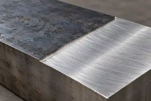
The recast layer is sometimes called the white layer. It forms because EDM melts a very small area of metal and the dielectric fluid cools it quickly. This re-solidified surface may have different properties from the base material and may include residual stress or microscopic surface cracks.
For many general tooling, profile, or static parts, this thin layer may be acceptable. For parts exposed to fatigue loading, repeated vibration, sealing pressure, corrosion risk, or high-stress service, the EDM surface condition should be reviewed more carefully.
Multiple finishing skim cuts can reduce the recast layer and improve surface finish. For critical parts, secondary processes such as light polishing, lapping, bead blasting, chemical treatment, or another agreed finishing method may also be reviewed before production.
Do not assume EDM always creates a finished surface ready for every application. Define whether the surface is acceptable as-EDM or whether a secondary finish is required.
For broader finishing, roughness, and post-processing planning, see our CNC surface finishes guide.
Thickness and Taper Can Affect Wire EDM Accuracy
Wire EDM tolerance is not the same on every material thickness.
A thin plate may be easier to cut with stable accuracy. A thick block may need more attention to taper, flushing, heat, wire path stability, and inspection.
| Part Condition | Tolerance Risk |
|---|---|
| Thin profile | Usually easier to cut and inspect |
| Thick plate | Higher taper and flushing risk |
| Tall narrow slot | Wire stability and flushing become important |
| Stacked plates | Efficiency may improve, but stack alignment must be controlled |
| Hard material | Cutting speed and surface condition may change |
| Thin wall | Handling and stress relief may affect final shape |
| Internal window | Start hole, tab removal, and corner radius need review |
| Long profile | Cumulative path accuracy and part support matter |
If a drawing includes a tight profile tolerance, the RFQ should include material, thickness, quantity, and whether taper inspection is required.
Datums and Inspection Method Matter
EDM parts can pass profile tolerance but still create assembly problems if the datum structure is unclear.
A wire EDM profile may be cut accurately, but if the part is located from the wrong surface during inspection, the report may not reflect how the part is assembled.
Before production, buyers should define:
| Drawing Detail | Why It Matters |
|---|---|
| Primary datum | Controls how the part is located during inspection |
| Functional edge | Shows which cut profile controls assembly |
| Hole-to-profile relationship | Important for pins, inserts, punches, and fixtures |
| Taper inspection | Needed for thick parts or tall profiles |
| Corner radius requirement | Prevents “sharp corner” disputes |
| Flatness or parallelism | May matter for plates and tooling inserts |
| Final surface condition | As-EDM, skim cut, polished, or coated |
| CMM / optical inspection | Defines how profile and position are verified |
The inspection method should match the functional feature. Optical inspection may work for some 2D profiles. CMM may be better for datum-related position checks. Surface finish or recast-layer checks may require other methods.
For broader inspection planning, see our quality assurance page.
Buyer RFQ Checks for EDM Tolerance Parts
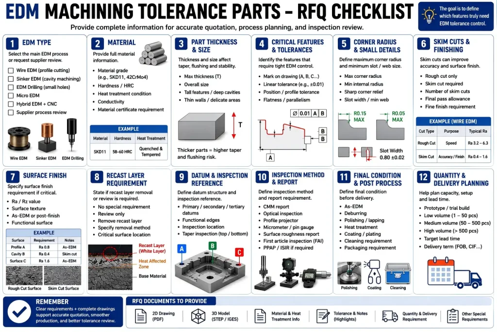
Before sending an EDM tolerance RFQ, buyers should define which features actually need EDM control.
| RFQ Check | What to Provide |
|---|---|
| EDM type | Wire EDM, sinker EDM, EDM drilling, or supplier review |
| Material | Grade, hardness, heat treatment, conductivity, and certificate needs |
| Part thickness | Especially important for wire EDM taper and flushing |
| Critical profile | Mark the features that need tight tolerance |
| Corner radius | Define maximum radius or functional relief requirement |
| Skim cuts | State if fine finish or tight profile control is needed |
| Surface finish | Ra/Rz or visual requirement if relevant |
| Recast layer | State if removal or review is required |
| Datum structure | Show how the part should be located for inspection |
| Inspection method | CMM, optical, gauge, profilometer, or customer report |
| Final condition | As-EDM, polished, heat-treated, coated, or cleaned |
| Quantity | Prototype, low-volume, tooling insert, or repeat production |
The goal is to define which features truly need EDM tolerance control, not to make every dimension ultra-tight.
Practical Drawing Note Examples
Example 1: Wire EDM Profile
Wire EDM profile tolerance: ±0.01 mm on marked contour. Corner radius 0.15 mm max unless otherwise specified. Inspect from Datum A and B.
This tells the supplier which profile matters, how tight it is, and how inspection should be located.
Example 2: Thick Plate Cutout
Wire EDM internal cutout. Taper to be reviewed. Final profile inspection required on top and bottom faces if needed.
This avoids assuming that a thick part behaves the same as a thin plate.
Example 3: Sinker EDM Cavity
EDM cavity surfaces as-EDM unless noted. Critical cavity width ±0.02 mm. Electrode wear and final surface finish to be reviewed before production.
This helps avoid confusion between cavity shape, surface condition, and final inspection.
Example 4: EDM Drilled Hole
EDM drilled hole Ø0.80 mm through. Position tolerance per drawing. Clean hole and inspect breakthrough edge.
This gives clear expectations for small-hole function and edge condition.
Example 5: Critical Surface Integrity
EDM surface on fatigue-critical area requires recast-layer review or removal method agreed before production.
This keeps the note flexible but makes the risk visible before machining starts.
Buyer Questions Before Choosing EDM
Is EDM always more accurate than CNC milling?
No. EDM can be more suitable for certain tight profiles, hard materials, small internal corners, and thin features. CNC milling may be better for open geometry, faster material removal, and simple features.
What tolerance can EDM hold?
EDM tolerance depends on EDM type, material, thickness, geometry, skim cuts, machine setup, surface finish, and inspection method. Very tight tolerances may be possible on selected features, but they should be reviewed before production.
Does wire EDM leave a burr?
Wire EDM usually does not create the same mechanical burr as milling, but the cut edge can still have recast material, edge condition concerns, or small tabs that need finishing.
Can EDM cut non-conductive materials?
Standard EDM requires electrically conductive material. Non-conductive materials usually need another process or a special reviewed method.
Do I need skim cuts for EDM tolerance?
Skim cuts may help improve accuracy and surface finish, especially for tighter wire EDM profiles. They add time and cost, so they should be used where function requires them.
Should I specify Ra or Rz for EDM surfaces?
If surface function matters, roughness should be defined clearly. Ra may be enough for some surfaces, while Rz or visual acceptance may be useful when peaks, valleys, sealing, or contact behavior matter.
What should I send for EDM tolerance review?
Send the 2D drawing, 3D model, material grade, thickness, heat-treatment condition, critical profiles, tolerance callouts, corner radius needs, surface finish requirement, recast-layer requirement if any, quantity, and inspection needs.
Rapid Efficient Support for EDM Tolerance Review
Rapid Efficient can review EDM tolerance requirements for wire EDM profiles, sinker EDM cavities, EDM-drilled holes, hard materials, thin features, tooling inserts, precision slots, internal cutouts, and complex conductive-metal parts.
We can help check whether EDM, CNC milling, grinding, turning, or a combined process route is more suitable for the part. We can also review corner radius, surface finish, recast-layer concern, datum setup, inspection method, and final delivery condition before quotation.
Send us your STEP file, 2D drawing, material, thickness, critical features, tolerance notes, EDM surface requirements, quantity, and inspection needs. Our team can review the manufacturing route and provide feedback before production.
For tolerance planning, see our CNC machining tolerances guide and tolerance stack-up guide.