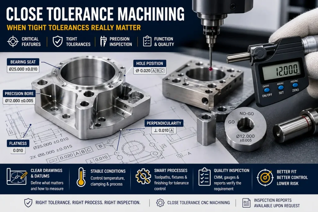
Close tolerance machining means producing selected part features within a narrow dimensional or geometric range.
But close tolerance does not mean making every dimension as tight as possible.
For CNC buyers, the real question is not only:
Can this part be machined to a tight tolerance?
The better question is:
Which features truly need close tolerance, and what process, material, fixture, inspection method, and final condition are required to prove them?
A close tolerance may be necessary for:
- bearing seats
- precision bores
- fitted shafts
- sealing faces
- datum-related hole patterns
- alignment surfaces
- sliding or rotating interfaces
- optical or sensor mounting features
- assembly-critical locations
- post-finish dimensions
It may not be necessary for every outer wall, pocket, chamfer, clearance hole, cosmetic face, or non-functional surface.
A good close tolerance drawing protects the features that control function. A poor close tolerance drawing makes the whole part harder to quote, machine, inspect, and accept.
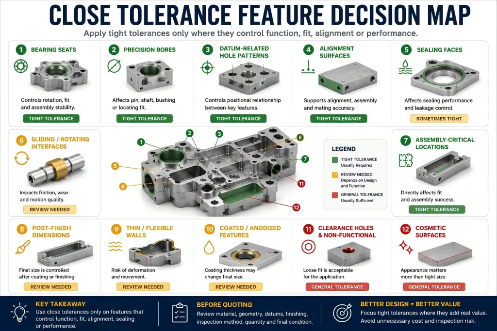
Close Tolerance Machining Is a Feature-Level Decision
Close tolerance machining should be applied to the features that affect fit, function, movement, sealing, alignment, or inspection.
It should not be copied across the entire drawing just to make the part look more precise.
| Feature Type | Close Tolerance Usually Makes Sense? | Why |
|---|---|---|
| Bearing seat | Yes | Controls fit, rotation, and assembly stability |
| Precision bore | Yes | Affects pin, shaft, bushing, or locating fit |
| Datum-related hole pattern | Yes | Controls positional relationship between features |
| Sealing face | Sometimes | Depends on flatness, roughness, and mating material |
| Cosmetic surface | Usually no | Appearance may matter more than tight size tolerance |
| General outside profile | Usually no | Often does not control function |
| Clearance hole | Usually no | Loose fit may already be enough |
| Thin flexible wall | Review first | The wall may move during machining or inspection |
| Coated or anodized feature | Review carefully | Final size may change after finishing |
| Plastic feature | Review carefully | Material recovery and temperature can affect size |
The most useful RFQ does not say “make all dimensions tight.” It identifies the few dimensions that must be controlled closely and explains why they matter.
For broader tolerance planning, see our CNC machining tolerances guide.
What Counts as “Close Tolerance” in CNC Machining?
There is no single universal number that defines close tolerance machining.
A tolerance that is easy on one part may be difficult on another part.
For example:
| Situation | Why the Same Tolerance Can Feel Different |
|---|---|
| Short aluminum pin bore | Easier to machine and inspect if the setup is rigid |
| Deep stainless steel bore | Tool reach, heat, and chip evacuation increase risk |
| Thin-wall aluminum housing | Clamping and material removal may move the wall |
| Large flat plate | Stress release and inspection support become important |
| Small brass turned part | Burrs and tool wear may affect final fit |
| PEEK or PTFE plastic part | Thermal movement and part recovery may affect measurement |
| Anodized aluminum feature | Coating thickness may change final size |
| Multi-face part | Setup transfer and datum alignment can create accumulated error |
A narrow tolerance is not only a number. It is a process decision.
The supplier must review whether the tolerance applies to:
- one feature or many features
- size only or geometric relationship
- before finishing or after finishing
- one sample or the full batch
- inspection at room temperature or shop-floor condition
- CMM inspection, gauges, micrometers, or functional fit checks
Close tolerance machining is realistic only when the process and inspection plan support the drawing requirement.
Close Tolerance vs Tight Tolerance vs Precision Machining
These terms are often used together, but they do not always mean the same thing.
| Term | Practical Meaning |
|---|---|
| Close tolerance machining | Selected features are held within narrow limits |
| Tight tolerance machining | Similar meaning, often used more generally |
| Precision machining | Broader term covering accurate machining, repeatability, surface quality, and inspection |
| High precision machining | Usually implies demanding tolerance, stable process control, and detailed inspection |
| General tolerance machining | Non-critical dimensions follow a standard tolerance class or agreed shop tolerance |
A precision-machined part may include some close tolerance features, but not every feature needs close tolerance.
A better drawing separates:
- critical features
- important but not critical features
- general tolerance features
- cosmetic features
- post-finish features
- inspection reference features
For service capability, review our precision machining services page.
What Makes Close Tolerance Machining Difficult?
Close tolerance machining becomes difficult when the part, material, fixture, tool, or inspection method cannot support the requested tolerance window.
The common drivers are:
| Driver | How It Creates Risk |
|---|---|
| Material movement | Aluminum, plastics, and stress-relieved stock can move after machining |
| Heat | Cutting heat can expand the part before inspection |
| Tool wear | Tool size and edge condition change during production |
| Tool deflection | Small tools, long tools, and deep features can bend under load |
| Workholding | Clamping force may distort thin walls or large plates |
| Datum transfer | Multiple setups can introduce alignment error |
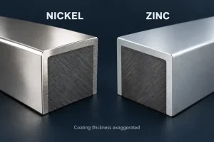
| Surface treatment | Anodizing, plating, heat treatment, or coating can change final dimensions |
| Burrs | Burrs can affect gauge fit, mating parts, and inspection results |
| Surface finish | Roughness can change how a fit feels or measures |
| Inspection access | Some features are hard to measure directly |
| Batch size | Repeatability becomes harder across many parts |
| Environment | Temperature and handling can affect micron-level features |
Temperature is another hidden factor in close tolerance machining. A part may look correct during machining, but if it is still warm from cutting, clamping, or handling, its measured size can shift slightly after it cools.
For critical tight features, the supplier may review whether the part needs stable cooling, a short stabilization period, or final inspection in a controlled measurement condition. This is especially important for precision bores, bearing seats, long flat surfaces, thin walls, and features measured in the micron-level range.
The goal is not to make every project overly complex. The goal is to avoid accepting a dimension that only looks correct under a temporary warm condition.
Close tolerance is not only about machine capability. It depends on the whole manufacturing route.
Material Behavior Changes the Tolerance Plan
The same close tolerance requirement can have very different risks depending on the material.
| Material | Close Tolerance Concern |
|---|---|
| 6061 aluminum | Good machinability, but thin walls and large pockets can distort |
| 7075 aluminum | Stronger and often stable, but stress and tool wear still matter |
| Stainless steel | Heat, work hardening, and tool wear need control |
| Brass | Machines well, but burrs and small threads still need review |
| Copper | Softness, smearing, burrs, and handling marks can affect final features |
| POM / acetal | Often suitable for precision plastic parts, but still needs stable inspection |
| PEEK | Stronger plastic option, but cost, geometry, and inspection conditions matter |
| Nylon | Moisture absorption may affect dimensions |
| PTFE | Softness, creep, and recovery can limit practical tolerance |
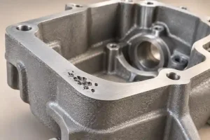
| Cast aluminum | Porosity and variable structure can affect local consistency |
A drawing tolerance should not be accepted without checking the material behavior.
If the same tolerance is used across aluminum, stainless steel, copper, and engineering plastic parts, the process route may need to change for each material.
Thin Walls and Large Pockets Need Extra Review
Thin walls are one of the most common reasons close tolerance machining becomes unstable.
A thin wall can move because of:
- clamping pressure
- cutting force
- heat
- residual stress release
- roughing sequence
- uneven material removal
- vibration
- tool engagement
- part handling
- inspection pressure
A wall may measure one way during machining and another way after unclamping.
For close tolerance thin-wall parts, the RFQ should define:
| Item | Why It Matters |
|---|---|
| Wall thickness | Helps evaluate deflection risk |
| Unsupported wall height | Tall thin walls are easier to move |
| Critical surface | Not every wall needs close tolerance |
| Datum reference | Defines how the wall should be inspected |
| Final condition | Machined, anodized, plated, painted, or assembled |
| Inspection method | CMM, height gauge, micrometer, optical, or fixture check |
| Quantity | Repeatability matters more in production |
| Assembly function | Explains why the tolerance matters |
Clamping force can also create hidden deformation. A thin wall may bend slightly while the part is held in a vise, fixture, or clamping system. The cutter may machine the feature correctly while the part is clamped, but after the clamps are released, the wall can spring back and change the final measured shape.
For close tolerance thin-wall features, the supplier may review soft jaws, vacuum fixtures, temporary support material, staged roughing and finishing, or lighter clamping force during the final pass. This does not mean every thin-wall part needs a special fixture, but flexible features should be reviewed before the tolerance is confirmed.
A tight tolerance on a thin wall is possible in some cases, but it should be reviewed as a process plan, not treated as a normal dimension.
Datum Structure Can Make or Break Close Tolerance Parts
Close tolerance machining is often less about one dimension and more about the relationship between several features.
For example, a bore may be easy to hold in size. But its true position relative to a datum face or another bore may be harder.
A useful close tolerance drawing should show:
- primary datum
- secondary datum
- tertiary datum
- critical feature IDs
- hole pattern relationship
- flatness or perpendicularity needs
- profile tolerance if needed
- inspection basis
- whether the part is inspected before or after finishing
Clear datums also help connect machining strategy with inspection strategy. This becomes important when the drawing includes true position, perpendicularity, parallelism, or profile tolerance.
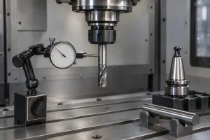
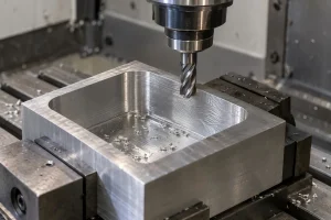
Even if the datum structure is clear, the machining route still matters. When an end mill enters a tight internal corner or a high-engagement area, cutting force can rise locally and cause small tool deflection. On close tolerance features, the supplier may review toolpath direction, corner feed reduction, finishing allowance, and datum-based inspection so that the machined feature and the measured feature are controlled from the same functional reference.
This is why close tolerance parts need both drawing review and process review. The datum tells the supplier what relationship must be protected; the machining plan controls how that relationship is produced.
If the datum structure is unclear, the supplier may measure the part differently from how the buyer expects the part to function.
For design and datum planning, see our CNC machining design guide.
Tolerance Stack-Up Can Create Assembly Problems
A single close tolerance feature may pass inspection and still fail in assembly if the surrounding features are not controlled correctly.
This is tolerance stack-up.
It can happen when:
- several loose dimensions add in the same direction
- two parts are inspected from different datum references
- coating thickness is not included
- hole position and hole size are treated separately
- flatness affects assembly but is not controlled
- burrs or edge breaks change the contact condition
- the mating part is not available during supplier review
A close tolerance should protect the assembly relationship, not just the isolated dimension.
For multi-feature assemblies, review our CNC machining tolerance stack-up guide before applying tight limits everywhere.
Close Tolerance and Surface Finish Are Connected
A dimension can be within tolerance but still perform poorly if the surface condition is wrong.
This matters for:
| Feature | Why Finish Matters |
|---|---|
| Sliding fit | Roughness affects friction and wear |
| Bearing seat | Size and surface quality work together |
| Sealing surface | Flatness and roughness can affect leakage |
| Press-fit area | Surface texture affects insertion force |
| Optical or sensor mount | Tool marks may affect seating or alignment |
| Cosmetic precision part | Tool marks may remain visible |
| Coated part | Pre-finish roughness can affect final appearance |
| Plastic part | Surface pressure can change measured dimensions |
A close tolerance feature may need both dimensional control and surface finish control.
If the part will be anodized, plated, passivated, polished, bead blasted, or painted, the drawing should say whether the tolerance applies before or after finishing.
For finish planning, see our CNC surface finishes guide.
Inspection Method Must Match the Feature
A close tolerance is only meaningful if the inspection method can verify it.
Different features may need different tools.
| Feature | Possible Inspection Method |
|---|---|
| Simple outside diameter | Micrometer |
| Simple inside diameter | Bore gauge, plug gauge, or pin gauge |
| Hole position | CMM or fixture-based inspection |
| Flatness | CMM, surface plate, height gauge, or optical method |
| Profile tolerance | CMM or optical inspection |
| Thread | Thread gauge |
| Surface roughness | Roughness tester |
| Thin wall | CMM, optical, or fixture check depending on access |
| Small slot | Pin gauge, optical inspection, or CMM |
| Assembly interface | Functional gauge or mating-part check |
A CMM is useful for many geometry-related features, but it is not automatically the best inspection tool for every close tolerance.
For report planning and feature checks, see our CMM inspection for CNC parts guide.
Shop-Floor Note: Tight Numbers Need Clear Conditions
A close tolerance number without a datum, final condition, and inspection method is not a complete manufacturing requirement.
Before quotation, the supplier should know:
- which feature is critical
- why it is critical
- what datum controls it
- whether finishing changes it
- how it will be inspected
- whether one sample or the full batch needs checking
- whether the mating part is available
- whether temperature or stabilization matters
This information can reduce avoidable quote revisions, machining risk, and inspection disputes.
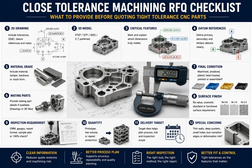
Buyer RFQ Checklist for Close Tolerance Machining
Buyers do not need to write the machining process. But they should provide the information that makes the tolerance review possible.
| RFQ Item | What to Provide |
|---|---|
| 2D drawing | Include tolerances, GD&T, datum references, and notes |
| 3D model | STEP / STP / IGES / X_T where available |
| Critical features | Mark which dimensions truly matter |
| Fit function | Press fit, slip fit, bearing seat, seal, alignment, sliding, or assembly |
| Material grade | Include temper, hardness, or stock form if known |
| Mating parts | Provide mating part details if available |
| Final condition | Machined, anodized, plated, heat-treated, polished, painted, or assembled |
| Surface finish | Ra value, cosmetic standard, sealing requirement, or functional finish |
| Inspection requirement | CMM, gauges, report format, sample plan, or 100% check |
| Quantity | Prototype, low volume, or repeat production |
| Delivery target | Helps plan risk, machining sequence, and inspection scope |
| Special concerns | Thin walls, deep pockets, small holes, burr-sensitive edges, or deformation |
The goal is not to ask for the tightest possible tolerance. The goal is to define which tolerances protect the part function.
Practical Drawing Notes for Close Tolerance Parts
Example 1: Bearing Seat
Bearing seat diameter applies after final machining and before surface treatment unless otherwise stated. Supplier to confirm inspection method before production.
This note defines timing and inspection responsibility.
Example 2: Hole Pattern
Hole pattern position tolerance applies relative to datum A, B, and C. Inspect critical pattern with CMM or agreed fixture method.
This prevents the hole pattern from being measured from the wrong reference.
Example 3: Thin-Wall Housing
Thin wall area shown in red requires supplier review for machining sequence, clamping method, and final inspection after unclamping.
This warns that the wall may move during or after machining.
Example 4: Post-Finish Feature
Critical bore size applies after anodizing. Masking, machining allowance, and post-finish inspection to be reviewed before production.
This avoids confusion between machined size and final delivered size.
Example 5: Mating Part Fit
Supplier to review fit requirement with customer-supplied mating component before confirming production tolerance.
This helps prevent a dimensionally acceptable part from failing in real assembly.
When Not to Request Close Tolerance
Close tolerance machining is not always the best choice.
Avoid unnecessary tight tolerances when:
- the feature is only cosmetic
- the dimension is a clearance envelope
- the mating part has large clearance
- the feature will be removed or changed by finishing
- the wall is flexible and has no defined inspection condition
- the cost increase does not improve assembly
- the inspection method is not defined
- the datum reference is unclear
- the tolerance is copied from another project without review
A looser tolerance on non-critical features can make the part easier to manufacture while keeping the important features protected.
Rapid Efficient Support for Close Tolerance Machining Review
Rapid Efficient can review close tolerance CNC machined parts before quotation and help identify which features need tighter control.
We can review material grade, critical dimensions, datum structure, surface finishing, burr risk, inspection method, quantity, and final delivery condition.
Depending on the project, inspection may include dimensional checks, CMM inspection, thread gauges, pin gauges, surface finish checks, and inspection reports according to the drawing requirement.
For manufacturability and tolerance planning, see our CNC machining design guide and precision machining services pages.
Send us your STEP file, 2D drawing, material grade, critical features, tolerance notes, surface finish requirement, quantity, and inspection needs.
Buyer Questions About Close Tolerance Machining
What is close tolerance machining?
Close tolerance machining means manufacturing selected features within narrow dimensional or geometric limits. It should be used for functional features, not automatically applied to every surface.
Is close tolerance machining the same as precision machining?
Not exactly. Precision machining is a broader term. Close tolerance machining focuses on selected tight dimensional or geometric requirements within a part.
Can every CNC part be made with close tolerance?
No. Feasibility depends on material, geometry, tool access, fixture stability, surface treatment, inspection method, quantity, and final application.
Should I apply the same tight tolerance to every dimension?
Usually no. Tight tolerances should protect important fits, datums, sealing surfaces, alignment features, or functional interfaces. Non-critical features can often use general tolerances.
Does CMM inspection prove the whole batch is good?
Not by itself. A CMM report proves the inspected features and samples. Batch quality still depends on sample plan, process control, production quantity, and agreed acceptance requirements.
What should I send for a close tolerance machining RFQ?
Send a 2D drawing, 3D model, material grade, critical features, datum references, tolerance requirements, final surface condition, inspection needs, quantity, and mating-part details if available.