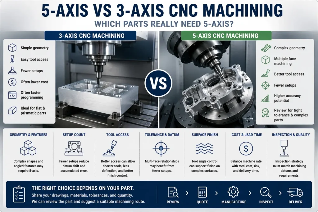
5-axis CNC machining is not automatically better for every part.
3-axis CNC machining is still the right choice for many plates, brackets, blocks, pockets, slots, holes, and simple precision surfaces.
The real question is not:
Is 5-axis CNC more advanced than 3-axis CNC?
The better question is:
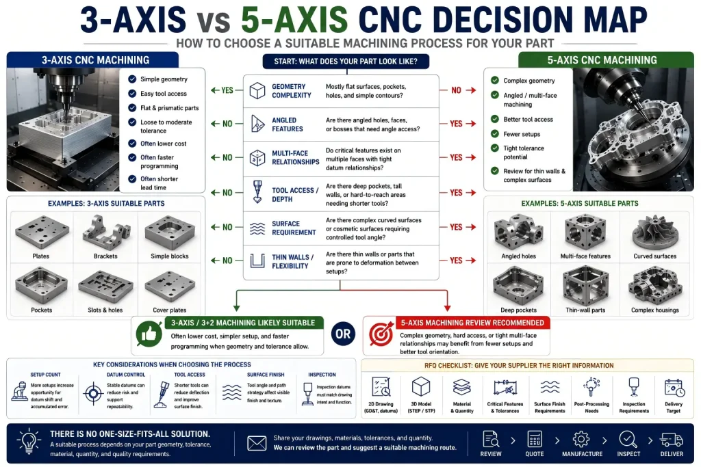
Does this part geometry, datum structure, tool access, tolerance requirement, surface finish, and production quantity actually need 5-axis machining?
A part may need 5-axis CNC when it has:
- angled holes
- multiple critical faces
- complex curved surfaces
- difficult tool access
- deep features that require shorter tools
- setup-sensitive datum relationships
- tight position tolerance across different faces
- features that are hard to machine accurately after repeated repositioning
- cosmetic surfaces where tool angle and surface continuity matter
A part may not need 5-axis CNC when it is mostly flat, prismatic, easy to access from one side, and can be machined accurately in one or two simple 3-axis setups.
The best machining method is the one that controls the part risk without adding unnecessary cost.
The Simple Difference: 3-Axis vs 5-Axis CNC
3-axis CNC machining moves the cutting tool along three linear axes:
- X axis
- Y axis
- Z axis
This is suitable for many flat, prismatic, and block-like parts.
5-axis CNC machining adds two rotary movements. Depending on the machine design, the tool or the workpiece can tilt and rotate, allowing the cutter to reach the part from more directions.
| Machining Type | Basic Motion | Practical Meaning |
|---|---|---|
| 3-axis CNC machining | X, Y, Z linear movement | Good for flat faces, pockets, holes, slots, simple contours |
| 3+2 machining | Tool or part is indexed to an angle, then cut with 3-axis motion | Good for angled features and multiple face machining without full simultaneous motion |
| 5-axis simultaneous machining | Linear and rotary axes move together during cutting | Good for complex surfaces, curved geometry, difficult tool access, and continuous tool angle control |
For buyers, the most important point is this:
5-axis does not only mean more axes. It means fewer repositioning steps, better tool access, and more control over tool angle when the part truly needs it.
For service capability, see our five-axis CNC machining service page.
When 3-Axis CNC Is Usually Enough
3-axis CNC machining is often enough when the part has simple access and stable geometry.
Common 3-axis suitable parts include:
| Part Type | Why 3-Axis May Be Enough |
|---|---|
| Flat plates | Most features are accessible from top or simple side setups |
| Simple brackets | Holes, slots, and pockets are usually easy to machine |
| Rectangular housings | If features are mostly on one or two faces |
| Simple pockets | Cutter access is direct |
| Basic cover plates | Surface finish and holes can often be controlled in 3-axis |
| Non-critical prototypes | Speed and cost may matter more than reducing setups |
| Simple aluminum blocks | Stable material and easy access reduce risk |
| Parts with loose tolerances | Repositioning may not create functional problems |
| Parts with one critical face | Datum control is easier |
| Parts with simple drilling | Holes are perpendicular to accessible faces |
3-axis machining can be accurate, repeatable, and cost-effective when the design supports it.
Do not choose 5-axis only because it sounds more advanced.
For many standard CNC parts, a clean 3-axis setup with good fixturing, sharp tools, and proper inspection can be the better manufacturing choice.
When 5-Axis CNC Starts to Make Sense
5-axis CNC machining becomes valuable when geometry, setup count, or tool access creates real manufacturing risk.
Typical 5-axis candidates include:
| Part Feature | Why 5-Axis May Help |
|---|---|
| Angled holes | The tool can approach at the required angle |
| Multi-face features | Fewer repositioning steps may protect datum relationships |
| Curved surfaces | Tool angle can follow the surface more smoothly |
| Deep pockets | Shorter tools may reduce chatter and deflection |
| Undercut-like access areas | Tilting can improve reach, depending on geometry |
| Impeller-style surfaces | Continuous tool orientation may be needed |
| Complex medical-style housings | Multiple precision surfaces may need fewer setups |
| Aerospace-style brackets | Angled bosses, pockets, and weight-reduction features can be difficult on 3-axis |
| Optical or sensor mounts | Datum relationships and surface angle may matter |
| Precision aluminum housings | Fewer setups may reduce accumulated positioning error |
5-axis is not valuable because the machine is impressive.
It is valuable when it reduces a real risk:
- setup error
- tool deflection
- long tool reach
- poor surface transition
- difficult angle access
- datum transfer error
- repeated clamping distortion
- inconsistent inspection reference
If none of these risks exist, 3-axis machining may still be the better option.
The Most Important Question: How Many Setups Are Needed?
Setup count is often the biggest difference between 3-axis and 5-axis CNC machining.
A simple 3-axis part may need only one setup.
A more complex part may need several setups:
- Machine top side
- Flip the part
- Machine bottom side
- Re-clamp for side holes
- Re-clamp for angled features
- Re-check datums
- Inspect each critical relationship
Every setup can introduce variation.
That does not mean multiple setups are bad. Good shops control them every day.
But each setup adds possible risk:
- clamping error
- datum shift
- part rotation error
- stack-up between faces
- fixture repeatability issue
- burrs or damage during handling
- extra inspection time
- higher labor cost
- longer lead time
5-axis CNC can reduce setup count when more faces or angles can be reached in one fixture.
The key question is:
Does reducing setup count protect a critical dimension, or does it only make the process look more advanced?
If the answer is “protect a critical dimension,” 5-axis review may be worthwhile.
5-Axis Is Not Always More Accurate
A common mistake is assuming 5-axis machining always means higher accuracy.
That is not true.
5-axis machining can improve process control in some cases, but accuracy still depends on:
- machine condition
- rotary axis calibration
- fixture quality
- tool length
- toolholder runout
- cutter rigidity
- CAM strategy
- operator setup
- part material
- clamping distortion
- inspection method
- datum structure
Multi-axis machining can also introduce error sources that are less obvious in simple 3-axis setups. Rotary axis calibration, center-of-rotation setting, pivot distance, machine warm-up condition, and volumetric compensation can all affect where the cutting tool actually contacts the part.
If these factors are not controlled, features machined at steep angles or far from the rotary center may show small position differences. This is one reason why 5-axis machining should not be treated as an automatic accuracy upgrade.
For some precision parts, a well-planned 3-axis process with stable fixturing and clear datum control may be more suitable than a poorly maintained or poorly programmed 5-axis process. The right choice depends on the part geometry, machine condition, calibration, fixture, and inspection plan.
A poorly planned 5-axis process can still produce bad parts.
A well-planned 3-axis process can produce very accurate parts.
The question is not whether 5-axis is “more precise” in a general sense.
The question is whether 5-axis reduces the specific risks created by this part geometry.
For tolerance planning, see our CNC machining tolerances guide.
Datum Transfer Error: The Hidden Cost of Multiple Setups
Datum transfer error happens when the part is moved from one setup to another and the reference system changes slightly.
This matters when features on different faces must align.
Examples:
| Feature Relationship | Risk in Multiple Setups |
|---|---|
| Hole pattern on top face and side face | Position may shift after re-clamping |
| Bore and angled mounting face | Datum reference may not match real assembly |
| Two opposite precision faces | Flip setup may create parallelism or thickness variation |
| Dowel holes across multiple faces | Small setup changes may affect assembly |
| Sealing face and side port | Face relationship may affect leakage or fit |
| Optical mount and sensor hole | Angle and position relationship may be hard to recover |
| Thin-wall housing with side holes | Clamping can move the wall between setups |
5-axis machining may reduce datum transfer risk by machining more features in one clamping.
But this only helps if the fixture, toolpath, and inspection method are planned correctly.
If the part still needs multiple setups, 5-axis alone does not remove the need for datum control.
For drawing and datum planning, review our CNC machining design guide.
Tool Access Can Decide the Process
Sometimes the reason to use 5-axis CNC is not tolerance. It is tool access.
A 3-axis machine may reach a feature only with a long tool.
Long tools can create:
- chatter
- deflection
- poor surface finish
- tapered walls
- low feed rate
- tool breakage risk
- poor chip evacuation
- higher machining time
- reduced repeatability
A 5-axis machine may allow the tool to tilt and reach the feature with a shorter, more rigid cutter.
This can help with:
- deep pockets
- tall walls
- angled faces
- side features
- complex ribs
- undercut-like access zones
- curved surfaces
- small internal radii in difficult areas
But tool access must be reviewed carefully.
Not every difficult-looking part needs simultaneous 5-axis machining. Some parts only need 3+2 indexing, simple angled fixtures, or better DFM changes.
3+2 Machining Is Often the Middle Ground
Many buyers think there are only two options:
3-axis or full 5-axis simultaneous machining.
In reality, 3+2 machining is often a practical middle ground.
In 3+2 machining, the machine indexes the tool or part to a fixed angle. Then it cuts using normal 3-axis motion.
This can be useful for:
- angled holes
- angled faces
- multiple side features
- machining several faces in one setup
- reducing custom fixtures
- improving tool access
- avoiding long tool stickout
3+2 may be more practical than full simultaneous 5-axis when the part does not require continuous tool movement around a complex surface.
| Requirement | Possible Process |
|---|---|
| Simple top pockets | 3-axis |
| Side holes on a block | 3-axis with second setup, 4-axis, or 3+2 |
| Angled holes | 3+2 or angled fixture |
| Multiple faces with datum concerns | 3+2 or 5-axis review |
| Continuous curved surface | 5-axis simultaneous review |
| Deep pocket with access issue | 3+2 or 5-axis review |
| Complex impeller-style geometry | 5-axis simultaneous |
3+2 machining can also be useful when surface finish consistency matters. During a 3+2 cut, the rotary axes are indexed to a fixed angle before cutting, so the cutting pass can behave more like a rigid 3-axis operation.
Full simultaneous 5-axis machining is valuable for complex surfaces, but the rotary and linear axes must move together during the cut. If acceleration, feed control, tool orientation, or machine dynamics are not well managed, the surface may show local dwell marks, small texture changes, or visible toolpath variation.
This does not mean 3+2 is always better. It means the supplier should review whether the part needs fixed-angle machining, full simultaneous motion, or a simpler 3-axis setup based on surface geometry, tolerance, tool access, and cosmetic requirements.
The best process depends on geometry, tolerance, quantity, and cost target.
Cost: 5-Axis Can Reduce or Increase Total Cost
5-axis machining often has a higher machine hourly rate than standard 3-axis machining.
But total cost is not only machine rate.
Total cost may include:
- setup time
- fixture cost
- programming time
- machining time
- inspection time
- scrap risk
- tool cost
- part handling
- rework risk
- lead time
- batch repeatability
5-axis may reduce total cost when it reduces setups, fixtures, rework, or inspection disputes.
5-axis may increase total cost when the part is simple and does not benefit from multi-axis access.
| Situation | Cost Direction |
|---|---|
| Simple flat part | 3-axis usually more cost-effective |
| One-sided prototype | 3-axis often faster and cheaper |
| Multi-face tight tolerance part | 5-axis may reduce setup and inspection risk |
| Complex curved surface | 5-axis may be necessary |
| Small quantity but complex geometry | 5-axis may reduce fixture time |
| High-volume simple part | 3-axis or dedicated fixture may be better |
| Deep features needing long tools | 5-axis may reduce chatter and tool issues |
| Cosmetic surface with complex angle | 5-axis may improve process stability |
A good RFQ should not ask only:
How much is 5-axis machining?
It should ask:
Which process gives the lowest total risk for this part?
Surface Finish: Tool Angle Matters
Surface finish is not only about Ra value.
It can also depend on tool orientation, cutter engagement, tool marks, vibration, and how the tool transitions across a surface.
5-axis CNC may help surface finish when the part has:
- curved surfaces
- angled surfaces
- blended faces
- deep cavity walls
- complex cosmetic surfaces
- areas where long tools would chatter
- surfaces where tool angle must be controlled
However, 5-axis does not automatically create a perfect surface.
Surface finish still depends on:
- cutter type
- feed rate
- toolpath strategy
- tool wear
- fixture rigidity
- material grade
- finishing allowance
- inspection standard
- polishing or post-processing after machining
For finish planning, see our CNC surface finishes guide.
Thin Walls and 5-Axis Machining
Thin-wall parts need special review regardless of axis count.
5-axis access may reduce some risks, but thin walls can still move because of:
- clamping force
- cutting force
- heat
- tool pressure
- residual stress release
- material removal sequence
- vibration
- inspection pressure
A 5-axis machine may help by reducing setup changes or improving tool access.
But if the wall is weak, unsupported, or poorly clamped, 5-axis machining can still create deformation.
For thin-wall parts, the supplier should review:
| Review Item | Why It Matters |
|---|---|
| Wall thickness | Controls deflection risk |
| Unsupported height | Tall thin walls move more easily |
| Fixture contact | Poor support can distort the wall |
| Roughing sequence | Uneven material removal can release stress |
| Final pass direction | Can affect wall finish and burr direction |
| Inspection condition | Part may measure differently after unclamping |
| Surface finish | Tool marks may become visible after anodizing or polishing |
| Quantity | Repeat production needs stable process control |
5-axis is not a cure for weak geometry. It is a tool that may help when the process is planned correctly.
Materials: Axis Choice Changes with Material Behavior
The same geometry may behave differently in aluminum, stainless steel, titanium, copper, brass, or engineering plastics.
| Material | Process Concern |
|---|---|
| Aluminum | Good machinability, but thin walls, chatter, and cosmetic tool marks need control |
| Stainless steel | Heat, work hardening, tool wear, and burrs may affect setup planning |
| Titanium | Heat and tool wear make tool access and rigidity important |
| Copper | Softness, smearing, and burrs can affect surface and edges |
| Brass | Machines well, but burrs, small features, and threads still need review |
| PEEK | Thermal movement and stress relief can affect dimensions |
| Nylon | Moisture and flexibility can affect inspection |
| PTFE | Softness and creep can limit tight tolerance results |
5-axis may reduce tool reach or setup count, but material behavior still controls the process risk.
A 5-axis strategy that works well for aluminum may not be suitable for stainless steel or engineering plastic.
Inspection Must Match the Machining Strategy
When a part is machined with multiple axes, inspection planning becomes important.
The inspection method should match the feature relationship.
| Feature | Inspection Concern |
|---|---|
| Angled hole | Angle and position relative to datum |
| Multi-face hole pattern | Datum relationship across faces |
| Curved surface | Profile tolerance or surface deviation |
| Sealing face | Flatness, roughness, and scratches |
| Precision bore | Size, roundness, and location |
| Thin-wall feature | Measurement after unclamping |
| Cosmetic surface | Visual standard and tool marks |
| Post-finish feature | Final size after anodizing, plating, or coating |
A common RFQ problem appears when machining and inspection do not use the same datum logic. A part may be machined in one 5-axis setup, but the CMM program still needs a stable and functional alignment strategy to verify the critical features correctly.
If the inspection alignment uses a weak cosmetic surface, an unimportant face, or a datum structure that does not match the drawing intent, the report may show apparent position variation caused by measurement setup rather than the machining process itself.
For multi-face features, angled holes, and true-position requirements, the RFQ should define the functional datums, inspection basis, and whether the CMM report should follow the drawing datum structure or an agreed inspection fixture strategy.
A CMM report may be useful for complex geometry, but the inspection plan must define what features are checked and from which datums.
For inspection planning, see our CMM inspection for CNC parts guide.
When 5-Axis Is Overkill
5-axis CNC machining may be unnecessary when:
- the part is mostly flat
- all features are accessible from one side
- tolerances are loose
- no angled features exist
- no critical multi-face relationship exists
- tool access is not a problem
- surface finish is not demanding
- the part quantity does not justify programming complexity
- a simple fixture can solve the problem
- 3-axis machining can meet the drawing requirement reliably
A 5-axis quote may still be possible, but it may not give the buyer better value.
For simple parts, the buyer may get faster quoting, lower cost, and easier repeatability with 3-axis machining.
When 5-Axis Should Be Reviewed Early
5-axis CNC machining should be discussed early when the part has:
- angled holes
- complex curved surfaces
- deep cavities
- tall walls
- difficult tool access
- multi-face datum relationships
- precision features on several faces
- cosmetic surfaces with complex geometry
- expensive material
- thin-wall areas
- tight position tolerance
- limited allowance for rework
- high cost of scrap
- post-processing that may reveal tool marks
In these cases, waiting until after the quote may cause delays.
The supplier may need to review:
- machining approach
- fixture plan
- CAM strategy
- datum structure
- inspection method
- tool access
- finishing route
- delivery target
The earlier these points are reviewed, the easier it is to choose between 3-axis, 3+2, and 5-axis machining.
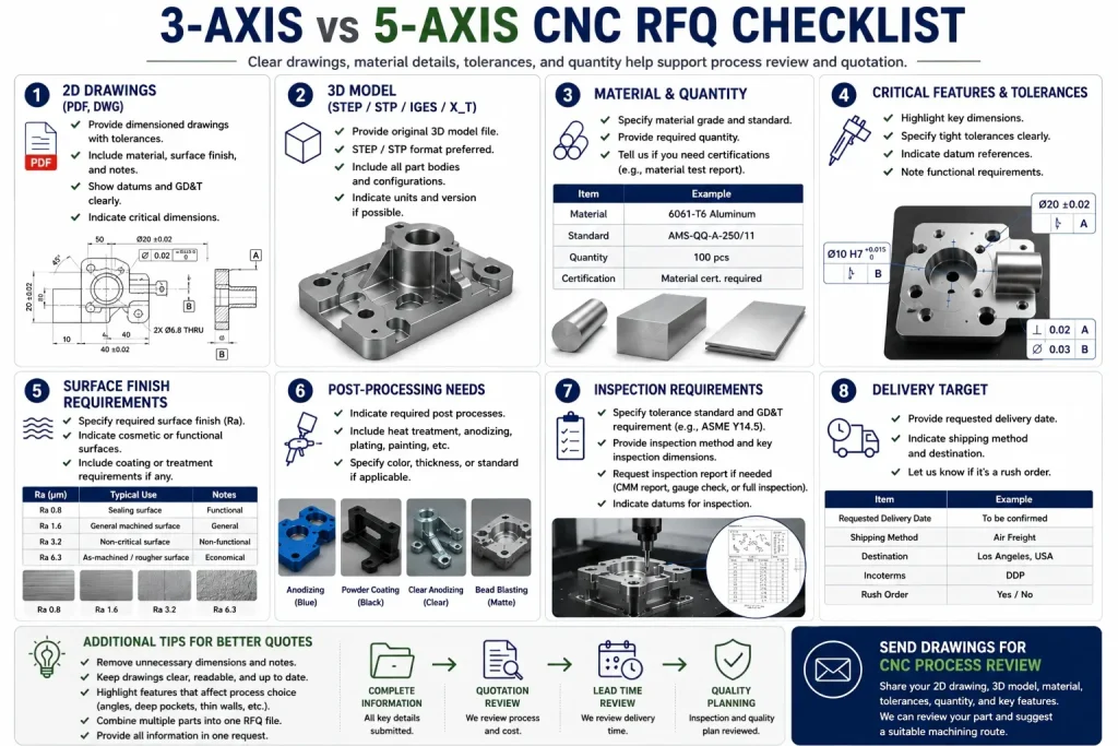
Buyer RFQ Checklist for 3-Axis vs 5-Axis Decision
Before requesting a 5-axis CNC machining quote, provide information that helps the supplier review the real process need.
| RFQ Item | What to Provide |
|---|---|
| 2D drawing | Dimensions, tolerances, GD&T, datum references, finish notes |
| 3D model | STEP / STP / IGES / X_T file |
| Critical features | Mark which features truly matter |
| Material grade | Aluminum, stainless steel, titanium, copper, brass, plastic, or alloy |
| Quantity | Prototype, low volume, or repeat production |
| Angled features | Holes, faces, bosses, slots, or ports that need angle access |
| Multi-face relationships | Features that must align across different faces |
| Deep pockets | Pocket depth, wall height, corner radius, bottom finish |
| Thin walls | Wall thickness, unsupported height, final inspection condition |
| Surface finish | Ra target, cosmetic standard, or visible surfaces |
| Post-processing | Anodizing, plating, passivation, polishing, coating, or heat treatment |
| Inspection needs | CMM report, gauges, first article inspection, or functional check |
| Mating parts | Assembly components, pins, bearings, seals, or reference parts |
| Delivery target | Helps review process route and fixture needs |
The supplier does not need the buyer to choose the machine first.
The supplier needs enough information to choose the process that controls the part risk.
Practical Drawing Notes for 5-Axis Review
Example 1: Angled Hole
Angled hole location and angle are function-critical. Supplier to review 3+2 or 5-axis machining approach before quotation.
This tells the supplier that the angle is not cosmetic.
Example 2: Multi-Face Datum Relationship
Hole pattern on side face must be controlled relative to datum A and B. Setup method and inspection plan to be confirmed before production.
This warns that datum transfer may matter.
Example 3: Deep Pocket
Deep pocket wall finish and bottom radius are functional. Supplier to review tool access, tool length, and chatter risk before machining.
This avoids forcing a long weak tool without review.
Example 4: Complex Surface
Curved surface profile must be inspected against 3D model. Supplier to confirm toolpath and inspection method before production.
This connects machining strategy with inspection.
Example 5: Thin-Wall Housing
Thin-wall areas require process review after roughing and before final finishing. Final inspection condition to be confirmed after unclamping.
This helps prevent measurement disputes.
Rapid Efficient Support for 3-Axis and 5-Axis CNC Review
Rapid Efficient can review custom CNC machined parts and help determine whether 3-axis, 3+2, or 5-axis machining is suitable for the project.
We can review:
- part geometry
- material grade
- critical features
- angled holes
- multi-face datum relationships
- thin walls
- deep pockets
- surface finish needs
- post-processing
- inspection method
- quantity
- delivery target
For complex geometry, angled features, and setup-sensitive parts, see our five-axis CNC machining service page.
For broader production support, review our CNC machining equipment and manufacturing capacity page.
If you are not sure whether your part needs 5-axis machining, send the STEP file, 2D drawing, material grade, tolerance notes, and quantity. We can review the part before quotation and suggest a suitable process route.
Buyer Questions About 5-Axis vs 3-Axis CNC
Is 5-axis CNC always better than 3-axis CNC?
No. 5-axis CNC is useful when geometry, tool access, setup count, or datum relationships create real risk. For simple flat or prismatic parts, 3-axis CNC may be more cost-effective.
Does 5-axis CNC always improve tolerance?
No. Tolerance depends on machine condition, fixture quality, tool length, material behavior, CAM strategy, and inspection method. 5-axis can help reduce setup-related risk, but it is not an automatic accuracy guarantee.
When should I choose 5-axis CNC machining?
Review 5-axis CNC when the part has angled holes, complex surfaces, deep pockets, multi-face datum relationships, difficult tool access, or critical features that would require several 3-axis setups.
What is the difference between 3+2 and 5-axis simultaneous machining?
In 3+2 machining, the tool or part is indexed to a fixed angle and then cut with 3-axis motion. In simultaneous 5-axis machining, rotary and linear axes move together during cutting. Many parts need 3+2, not full simultaneous 5-axis.
Is 5-axis CNC more expensive?
It often has a higher machine rate and programming requirement, but it may reduce total cost if it reduces setups, fixtures, scrap risk, and inspection problems. For simple parts, 3-axis is often more cost-effective.
What files should I send for 5-axis CNC review?
Send a 3D model, 2D drawing, material grade, critical features, tolerance notes, surface finish requirement, post-processing needs, quantity, and inspection requirements.