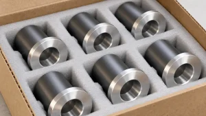
A plastic housing milled from plate may have a thick mounting rim, solid screw bosses, and a precision bore. Sending that CAD file for injection molding can change more than the quote. The thick sections may need coring, walls may need draft, and the critical bore may still need machining.
CNC machining removes material from a stock shape. Injection molding fills a mold and releases the cooled part. Machining often suits limited quantities, changing designs, and accessible features in an available stock grade. Molding can reduce repeated cutting work when the design, material, and demand justify tooling. A molded blank with selected machined surfaces provides a third option.
The comparison should therefore cover the finished plastic part, including any design changes and secondary operations needed to meet its requirements.
Follow the Housing Through Two Different Starting Shapes
Consider a small equipment housing with an open pocket, mounting bosses, a cover seating face, and a locating bore. This is a representative design example, not a reported customer project.
Starting from plate, the shop removes the pocket and leaves material around the mounting features. A thick local section can be straightforward to retain. Closely spaced ribs can take more cutting time because the tool must remove the material between them while maintaining access and support.
A molded version starts with a different constraint: resin must fill the cavity, cool, and leave the tool. Keeping the machined design’s solid bosses and heavy wall intersections may create difficult cooling conditions and increase the risk of sink or internal voids.
| Housing feature | Machining from stock | Review before injection molding |
|---|---|---|
| Thick mounting boss | Leave the boss while cutting the surrounding pocket | Consider a hollow boss with ribs or gussets; verify screw support and local section thickness |
| Deep pocket and internal corners | Check cutter reach, corner radius, and wall support | Check core geometry, draft, filling, and ejection |
| Cover seating face | Machine the face relative to the assembly datums | Keep gate and ejector marks away where necessary; assess flatness and possible finish machining |
| Locating bore | Machine size, form, and position from the chosen setup | Review draft, shrinkage, core support, and whether the bore should be finished after molding |
| Side opening | Add a cutting setup if access requires it | Review parting direction, a side core, a design change, or secondary machining |
Preserve the functional interfaces while allowing the surrounding geometry to suit the manufacturing route.
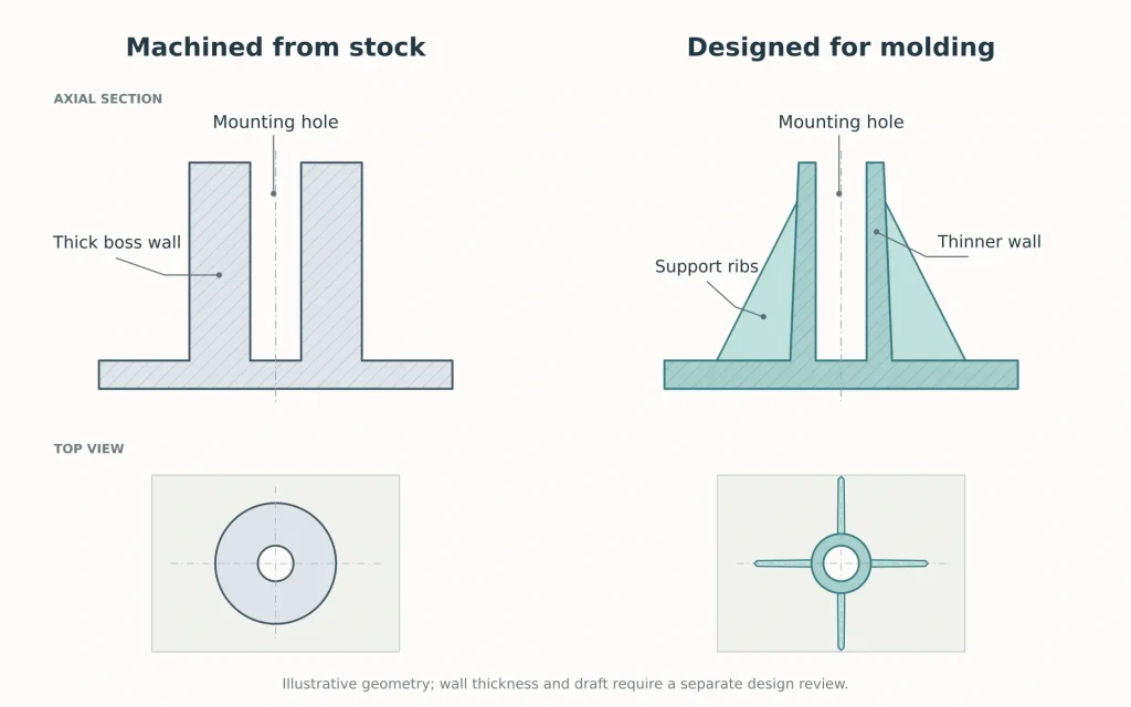
A hollow boss supported by ribs may replace a solid machined boss, but the change still needs structural review. Removing material changes stiffness and the load path. Protolabs’ boss-design guidance explains why bulky boss-to-wall connections deserve attention and why support ribs can be useful.
The release path needs its own check. A side feature that is easy to mill may require a mold mechanism. Our undercut release guide explains the alternatives without assuming every trapped feature needs a slide.
Check What “The Same Plastic” Actually Means
A stock shape and an injection-molding resin can share a polymer family without being equivalent purchasing specifications.
For the machined route, identify the stock manufacturer’s grade, its form and size, and any specified treatment. For molding, identify the resin grade, reinforcement, additives, and color requirements. Then confirm which properties the application actually needs.
A required resin may be available as pellets but unavailable as a suitable plate or rod. Conversely, a machinable stock material may use a production route that does not translate to ordinary injection molding. Availability should be checked before treating both options as feasible quotations.
Material history matters as well. Stock production and molding can produce different internal stresses and, for reinforced grades, different fiber orientations. A machined sample should not automatically be treated as an isotropic reference or as a prediction of the molded part’s strength.
Machining itself can release residual stress, particularly when a large amount of material is removed unevenly. Ensinger’s machining and annealing guidance discusses these effects and the circumstances in which an intermediate annealing step may help. Any treatment should follow material-specific guidance and be included in the manufacturing route.
For moisture-sensitive materials, agree on the condition used for dimensional and functional acceptance. An uncontrolled difference between a dry sample and a conditioned production part can obscure the process comparison.
Our plastic machining material guide covers the broader selection differences among common engineering plastics.
A Critical Bore Can Justify a Combined Route
The housing’s outer walls may be suitable for molding while one locating bore needs closer control of size, form, or position. That does not automatically require machining the entire housing from solid stock.
A combined route can mold the main shape and then machine the bore and selected seating surfaces. The molded blank needs to be designed for that operation, including tool access, workholding, and enough material around the finished features.
Choose the surfaces to finish before deciding where the molded blank will be located and clamped.
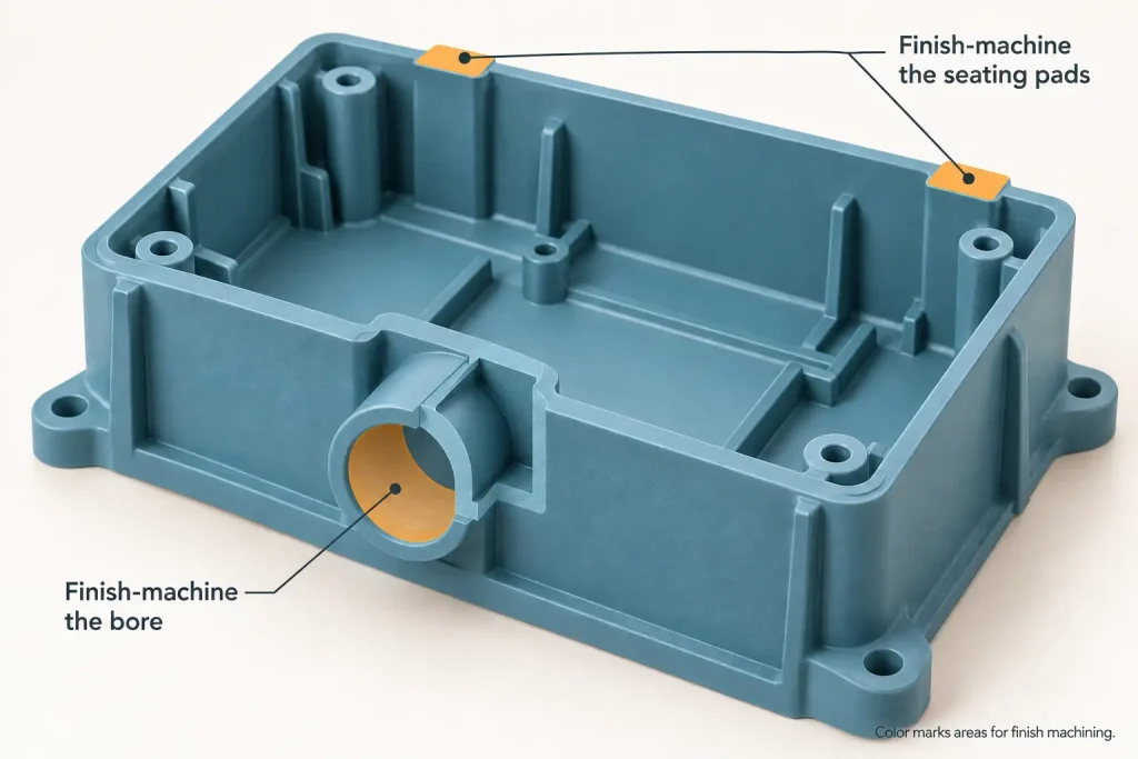
For example, boring a hole accurately relative to a fixture does not establish its position relative to the housing’s assembly face unless the setup relates the two correctly. An irregular molded surface is a poor locating choice when its variation moves the bore away from the required datum relationship.
The machining allowance also needs a range. A nominally undersize molded hole can still lack cleanup stock on one side if it shifts or distorts. Excess stock can increase cutting load and the amount of stress released. Evaluate the expected blank variation around the intended finished surface.
Clamps should hold the blank without forcing a flexible housing into a shape it loses after release. Where temperature stabilization, moisture conditioning, or heat treatment affects the final dimensions, agree on its place in the sequence.
This route adds another setup, handling, and inspection. It earns its place when reducing bulk machining or simplifying selected molding requirements outweighs those added operations. It cannot repair every molding defect or compensate for a poorly supported part.
Count the Stock Removed, Then Price the Whole Route
The finished part’s weight can hide a large difference between machining from stock and molding near the final shape.
Consider an illustrative rectangular blank measuring 80 × 60 × 20 mm:
- Blank volume: 80 × 60 × 20 = 96,000 mm³ = 96 cm³.
- Assumed finished-part volume: 24 cm³.
- Material removed: 96 − 24 = 72 cm³.
- Geometric stock utilization: 24 ÷ 96 = 25%.
This example excludes saw kerf, unused stock remnants, and rejected parts. It describes material volume, not a supplier quote or an industry benchmark.
Removing 75% of the blank does not mean that molding will reduce the total cost by 75%. Stock and pellets have different purchase costs. Molding also carries tooling, setup, validation, and production costs, and may consume material in runners, purging, or rejects.
The example identifies a question worth asking: how much of the CNC price comes from buying stock and removing material that the final part does not contain?
A simple spacer cut from appropriately sized tube may have little material waste. A deeply pocketed housing cut from a thick plate may present a different opportunity. Part count alone misses that distinction.
Request prices for the actual proposed routes: the released machined design, the reviewed molded design, and a molded-plus-machined version where justified. Each price should end at the same agreed acceptance state, including required finishing, inserts, conditioning, and inspection.
Compare the first order separately from repeat orders. Molding adds tool preparation and sample approval before production. CNC machining may avoid a dedicated mold, but still needs stock, programming, fixtures, and setup. Neither the molding cycle time nor the CNC cutting time represents the complete delivery schedule.
Use credible demand for the approved design when evaluating tooling. There is no universal quantity at which every plastic part should move to molding, and machining can remain the production route when its geometry, material, or demand favors it.
Decide Which Prototype Results Can Transfer to Production
A machined prototype can provide useful evidence about fit, access, assembly sequence, and selected performance requirements. Its value depends on what was tested and how closely its material and geometry represent the proposed production part.
For the housing, a successful cover fit supports the interface design at the sample’s measured dimensions. It does not establish how flat the molded seating face will be across cavities and production batches.
Likewise, a load test on a solid machined boss does not approve a redesigned hollow boss. If the molded version changes the section, resin grade, fiber orientation, or local weld-line conditions, assess the affected performance again.
Record those differences in the approval plan. Identify which results remain useful, which need confirmation on molded samples, and which depend on the full route including secondary machining.
When the production part is molded and then machined, inspect the final component after both operations. Check the bore’s relationship to the assembly datums as well as its diameter. If the part will be accepted in a defined free or restrained condition, state that condition rather than changing support until the measurements pass.
For a route review, send the current machined design, the proposed molding changes, the stock and resin grades under consideration, and the surfaces that must retain their assembly function. Include the first-order quantity and realistic repeat demand. RapidEfficient can review CNC machining and injection molding requirements together, including whether selected surfaces should be machined after molding.