Knurling creates a repeating pattern of ridges on a part, commonly to improve hand grip or help retain the part in another material. The pattern can be formed by displacing material or cut by removing it. That difference affects the machining load, the starting diameter, and the space needed around the feature.
Common patterns include straight ridges running along a cylinder, diagonal ridges, and crossed ridges forming a diamond pattern. The pattern describes the surface, but a drawing also needs to explain what that surface must do.
For a CNC component, “diamond knurl” can leave several decisions open: how coarse the texture should be, where it must stop, which diameter applies, and whether acceptance depends on appearance, hand grip, or assembly retention.
One Adjustment Knob, Several Surface Requirements
Consider an illustrative metal adjustment knob with a knurled outer band, a smooth locating bore, and a shoulder beside the band.
The outer band provides grip. The bore locates the knob on its shaft. The shoulder may establish an axial seating position. Giving these surfaces separate requirements helps the manufacturer protect the features that control assembly.
| Feature on the knob | Requirement to define | What to check on the finished part |
|---|---|---|
| Knurled grip band | Pattern, pitch, band length, acceptable tooth sharpness, and any required diameter over the crests | Texture continuity, damaged or loose edges, grip feel, and the specified diameter |
| Smooth locating bore | Bore size and relevant form or alignment requirements | Bore condition after knurling and any later finishing |
| Shoulder beside the band | Required seating face and permitted knurl termination or relief | Unwanted raised material, burrs, or tool marks at the seating surface |
| Ends of the grip band | Start and stop locations, transition shape, and edge requirements | Incomplete teeth, sharp edges, and interference with neighboring components |
The knurled band should carry the grip requirement; the locating surfaces should carry the assembly requirements.
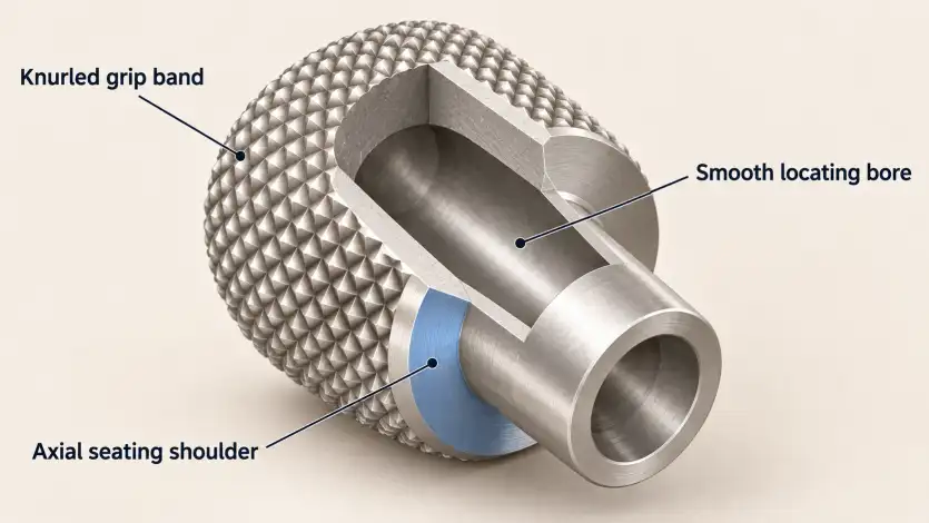
A hollow knob also brings the bore into the manufacturing decision. Forming the outside pattern applies load to the wall, so the process sequence and support should be reviewed before the bore receives its final acceptance inspection.
The broader relationships between bores, shoulders, and external features belong in the complete CNC turned-part design, rather than being left to the knurl note alone.
Form Knurling and Cut Knurling Change the Manufacturing Route
Form knurling
Form knurling presses patterned wheels into the surface. Material moves into the developing ridges, increasing the outside diameter.
The material must tolerate the required cold deformation. Its condition matters alongside the alloy name: a route suitable for one hardness or heat-treatment condition may be unsuitable for another.
The forming load also matters. A slender shaft, thin sleeve, or unsupported section may deflect or distort during the operation. Tool arrangement and workpiece support can reduce these problems, but the surrounding geometry still needs review.
Cut knurling
Cut knurling removes material to generate the pattern. It produces much less material displacement and can be useful where forming loads would be difficult to support.
Cutting forces remain present, and the tool still needs a workable entry and travel path. Available patterns and access near shoulders depend on the selected tool system.
Hommel+Keller’s form and cut knurling comparison explains the different material behavior and tooling restrictions.
For the adjustment knob, a thin wall may make cut knurling worth evaluating. A short band next to a large shoulder may create a different constraint: the tool must reach the entire required band without contacting the shoulder.
Material condition, wall support, and tool access should be reviewed together before choosing the process.
Where either method can meet the functional requirements, leaving the process open can give the supplier more practical tooling options. Specify the method when it is necessary for the material, geometry, or approved manufacturing route.
Blank Diameter and Finished Diameter Are Different Requirements
A knurled feature can have several relevant diameters:
- Blank diameter: the smooth cylinder prepared before knurling.
- Diameter over the crests: the outside envelope of the finished pattern.
- Root diameter: the diameter at the valleys between the teeth.
For a formed knurl, the crests rise above the original surface while the tool penetrates below it. The resulting size depends on the pattern, material, tool geometry, and process settings.
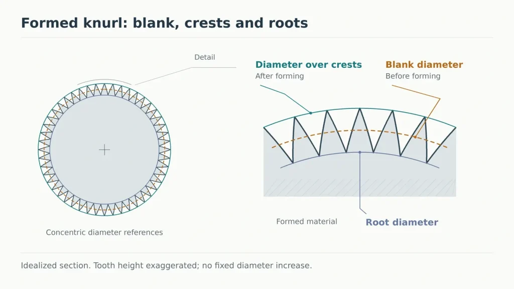
If the drawing controls the finished outside envelope, the supplier needs to select a suitable starting blank diameter. A single fixed reduction should not be applied to every knurled part. Manufacturer calculations or tables provide a starting point, followed by confirmation under the intended production conditions.
PMPA’s knurl drawing guidance recommends specifying maximum and minimum after-knurl dimensions when a particular finished size is required.
Label a critical diameter as an after-knurl requirement and identify whether it applies before or after the final surface treatment.
This becomes important when a knurled band must pass through an opening or engage another component. An acceptable diameter before knurling does not establish the final clearance.
For cut knurling, lower material displacement simplifies part of this problem, but the final crest condition, burrs, and subsequent coating still belong in the acceptance check.
Pitch and Tracking Need Clear Definitions
“Fine,” “medium,” and “coarse” can communicate a general appearance preference. They do not provide a precise, universally interchangeable tooth spacing.
Where consistency matters, identify the pitch system and units. Knurling tools may be described using metric pitch, teeth per inch, or diametral pitch. These designations use different conventions; similar numbers do not make them equivalent.
For diagonal patterns, the direction in which spacing is measured also matters. Use the selected standard or tool specification consistently rather than converting a drawing by comparing labels alone.
During form knurling, the wheel must follow the developing pattern as the workpiece rotates. If it begins making additional tracks between the intended ones, the result may show doubled or irregular teeth.
That condition should trigger a review of blank diameter, tool pitch, alignment, penetration, and tool condition. It should not simply be accepted as a finer texture. A circumference-based calculation can help select a blank, but it does not replace confirmation with the actual material and tooling.
The band ends need similar attention. State where a complete pattern is required and where a transition or relief is allowed. Requiring fully developed teeth against an inaccessible shoulder can force a different tool or an additional operation.
If the teeth must mate with a precisely defined toothed counterpart, specify the required tooth geometry and applicable standard. A general grip-knurl note does not define a precision spline or serration.
Approval Depends on How the Knurl Is Used
For a hand-operated knob, review the finished texture under the intended use conditions. A pattern that feels acceptable with gloves may be uncomfortable on bare fingers. Tooth sharpness, damaged edges, cleaning requirements, and the final coating can all affect the result.
An approved sample can help communicate appearance and feel. It should accompany measurable requirements where size, band location, or assembly clearance matters.
A retention knurl needs a different approval method. When teeth engage a mating material, the result depends on both components: the crest size and tooth form, the receiving hole, the material properties, and the engagement length.
Smooth-shaft press-fit tolerance principles provide useful background, but a knurled interface adds local deformation around the teeth. Retention should therefore be evaluated with the intended mating material and assembly process.
Specify the functional result that matters. Resistance to rotation and resistance to axial withdrawal are separate requirements; passing one test does not establish the other. Where relevant, also check insertion force and damage to the receiving part.
A diameter measurement alone cannot establish these results. Likewise, a visually consistent pattern does not prove that a hollow component retained its bore size during forming.
For a knurled component review, mark the band location, pattern and pitch, required finished diameter, neighboring fit surfaces, and final treatment on the drawing. Explain whether the feature is used for hand grip or retention, and include the mating-part details where applicable. Through our CNC turning services, Rapid Efficient can review the proposed knurling route, access, and inspection requirements before quotation.