
Keyway machining should be specified around the fit of the shaft, key and hub. Slot width matters, but so do the two slot depths, the key’s end shape and the space available to cut the internal feature. These details determine whether separately purchased parts can form the intended connection.
Consider an illustrative assembly designed for a sliding shaft-to-hub fit. The hub slides onto the shaft during a check without the key, then stops short when the key is fitted. Several causes are possible: a width mismatch, a key standing too high, interference at a slot end, or a burr. Filing the key until that one assembly fits could hide the cause and make replacement parts harder to control.
Before comparing quotations, decide whether the order is for an approved matched assembly or for parts that must interchange without selective fitting. The following review concerns ordinary parallel sunk keys. Taper keys, Woodruff keys and splines have different geometry and fitting requirements.
Where the Key Contacts the Shaft and Hub
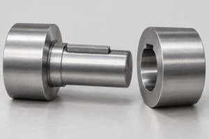
The shaft keyseat is the external recess that holds part of the key. The hub keyway is the internal slot that receives the projecting part. Suppliers sometimes use “keyway” for both, so identify the component on each drawing and inspection record.
In an ordinary parallel-key connection, torque passes through contact at the key’s side faces. The loaded faces depend on the direction of torque. Clearance above the key allows the specified side fit to work without wedging the key between the shaft and hub. The shaft diameter and hub bore retain their own fit requirements; the key is not a remedy for an incorrect bore.
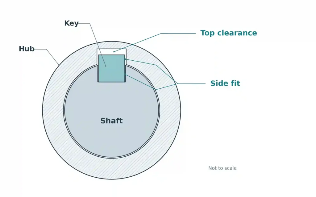
Review the connection as three linked specifications:
- Shaft keyseat: width and tolerance, depth with its measurement reference, axial position, end shape and permitted corner radii.
- Key: the specified standard and form, or a complete part drawing; width, height, length, material, end shape and edge details.
- Hub keyway: width and tolerance, depth with its measurement reference, axial extent, entry details and the permitted termination geometry.
Keep the applicable drawing revisions together and identify who supplies the key. A quote for a shaft and hub may exclude that purchased component.
The shaft and hub slots need their own depth definitions. A radial depth from the original cylindrical surface differs from a measurement between the slot surface and the opposite side of the shaft or bore. ELESA+GANTER’s DIN 6885/1 keyway diagrams illustrate these separate dimensions. Use the standard edition and tolerances specified for the order, with the measurement endpoints shown clearly.
Choosing one tight tolerance for every width can create assembly difficulty rather than a better connection. The intended shaft-to-key fit and hub-to-key fit should be specified separately. Also identify how the hub will be held axially. Transmitting torque through a key does not, on its own, define an acceptable axial retaining arrangement.
Follow the Keyway to Its Ends
A cross-section can show acceptable widths and depths while missing an interference farther along the shaft. Check the key, both slots and the final hub position in a longitudinal view as well.
A closed shaft keyseat made with an end mill has rounded ends in plan view. The proposed key must fit that shape. For a square-ended key, check clearance at the rounded slot ends rather than matching nominal lengths alone. At the slot bottom, the permitted corner radius and the key’s edge relief must also allow the key to seat correctly.
Now place the hub at its final axial position. Identify the straight side-face overlap available between the key and each mating slot. Rounded ends, reliefs and any portion extending beyond the hub affect that overlap. Overall slot length and usable key engagement are different quantities. Required engagement must come from the connection design, including its loads and materials; a successful assembly check does not establish torque or fatigue capacity.
The approach to that final position matters too. A shoulder, a blind slot end or an entry edge may stop the hub before it reaches its locating face. Show which end the hub enters from and any assembly restrictions. If a longer slot, altered key or extra relief is proposed, check the revised geometry against both assembly and the required engagement before approving it.
For a replacement hub, the existing shaft and key dimensions are therefore part of the enquiry. If their condition or identity is uncertain, agree how they will be measured before releasing the replacement drawing.
How the Internal Keyway Will Be Cut
Look at where the internal slot ends, even when the hub has a through-bore. The bore can pass through while the keyway stops inside it. That remaining material changes the tool’s exit and withdrawal options.
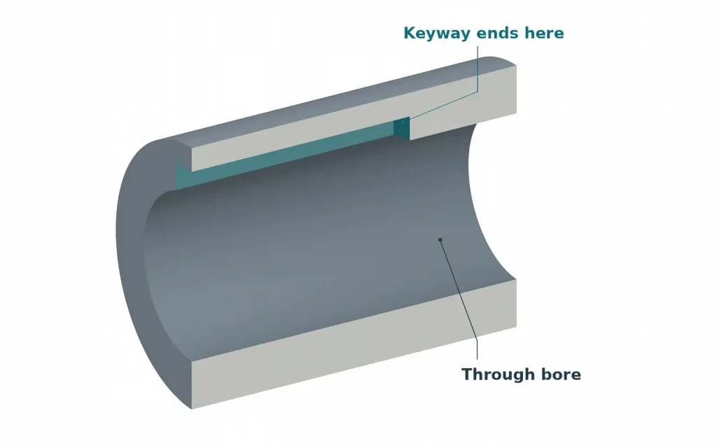
For a conventional through-broaching route, the supplier must accommodate the broach, its guide and the required exit space. A blind termination calls for a different tool and motion plan. Suitable CNC single-point broaching or slotting methods can make blind keyways, provided the cutting stroke, withdrawal and chip removal are feasible.
CNC Broach Tools’ blind-keyway guidance shows relief arrangements for its inserted tools, including grooves and cross-holes. Such features give the cutter room to finish its stroke and help manage chips. Their dimensions must suit the selected tool and setup. Adding a cross-hole or relief changes the part and requires design approval; it should appear in the quoted drawing revision.
EDM may provide another route for an electrically conductive part. Wire EDM needs a suitable through-path that preserves the required material. Sinker EDM needs access for the electrode and effective flushing. The sinker EDM versus wire EDM comparison explains those access boundaries. Naming EDM alone leaves the actual slot-end geometry unresolved.
Compare quotations against the same approved keyway. Include any special tooling, relief preparation and required finishing in the scope. A lower price based on an extended slot or a new access hole represents a different part until that change is accepted.
Submit the shaft drawing, hub drawing and key specification or part number together for a CNC machining review. Mark the slot ends and surrounding regions that must remain unchanged, and identify whether the mating components are supplied for checking. This lets the proposed machining route be assessed against the complete connection.
Inspect from the Shaft or Bore Axis
The inspection plan should establish the shaft or bore datum required by the drawing, then evaluate the keyway relative to it. Checking slot width alone leaves its position and alignment unresolved. Where orientation to another keyway, flat or hole matters, include that angular relationship explicitly.
Agree how width and depth will be measured, including any locations needed along the slot. A single reading near the entrance can miss variation deeper inside. Select probes or gauges that can reach the required surfaces, and distinguish straight walls from end radii, corner radii and burrs when interpreting measurements.
Inspect the finished condition required for assembly. Deburring should clear the entry and edges while preserving the specified contact surfaces. Any later coating or treatment that affects the fit belongs in the final dimensional requirements and inspection sequence.
A first-article assembly check adds useful evidence: the key seats as intended, the hub reaches its required position and the specified retaining arrangement can be fitted. Record which shaft, hub and key were used and any permitted fitting work.
For interchangeable supply, combine that check with dimensional acceptance of the individual components under the agreed inspection plan. One selectively fitted set cannot demonstrate that separately ordered replacements will fit. For an approved matched set, identify the paired components and document any allowed adjustment. The delivery requirement should make clear which of these two outcomes the buyer is purchasing.