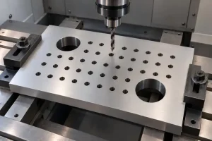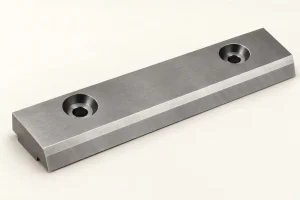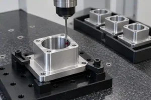

A CNC order can contain hundreds of repeated holes and only a few different diameters. Another order can contain fewer holes but need several sizes, entry conditions and bottom shapes. Those jobs do not present the same drilling-versus-milling decision.
Drilling is often a practical starting point for repeated holes that suit the available drill. Milling can be useful when diameter variety or local geometry makes that drill route less suitable. A single part can use both. Here, the comparison is between hole-making operations on a CNC machining center; the machine can perform either operation.
Diameter Variety and Hole Repetition
In conventional drilling, the rotating drill advances along the hole axis. Its cutting diameter largely determines the opening it produces. In interpolated hole milling, a smaller rotating cutter follows a circular path around the hole axis. Adding axial movement produces a helical entry into the material.
That difference changes the tool list. Several drilled diameters may require several drills. A suitable end mill can cover a range of hole diameters by changing its path. It cannot cover every diameter or depth: the cutter must be able to enter the material, clear the center, reach the required surfaces and remove chips.
For repeated holes of one size, ask whether an appropriate drill is already available and can complete the cut under the proposed conditions. For a few larger or unusual diameters, ask whether existing milling tooling offers a practical alternative. Sandvik Coromant’s hole-making guidance identifies diameter variety, tool-magazine space and production quantity among the reasons to consider milling.
Keep the cutter-path calculation separate from this purchasing decision. The helical milling guide explains the relationship between hole diameter, cutter diameter, pitch and feed. A supplier proposing one milling cutter for several hole groups still needs to check each group against that tool’s limits.
Find the Holes That Need More Than a Straight Drill Cycle
Group holes by their entry, depth, exit and bottom requirements as well as their diameter. Two holes with the same nominal diameter may need different preparation or tooling.
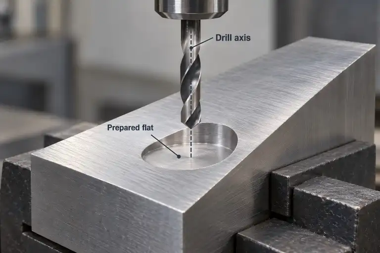
An inclined or curved entry can require preparation. The cutting edges of a drill may engage unevenly, increasing deflection and edge-loading risks. One possible route is to mill a small flat before drilling, if the part design allows that local material removal. Another is a drill selected for the actual entry condition. The exit surface matters too. Sandvik’s irregular-surface drilling guidance separates these recommendations by drill type; it does not make every sloping surface a reason to reject drilling.
A blind hole needs an agreed bottom shape. With an ordinary pointed drill, the deepest point extends beyond the full-diameter cylindrical portion. Confirm the usable cylindrical depth and the minimum material that must remain below the deepest machined point. Simply drilling deeper to obtain more full-diameter depth can violate the retained floor.
A flat floor may be produced by a suitable milling operation, a purpose-designed flat-bottom drill, or a separate bottom-finishing operation. “Flat bottom” therefore does not select milling by itself. The proposed tool must suit the required floor, corner geometry, depth and material. A milled floor also needs an appropriate tool and finishing path to meet its stated requirements.
A deep, narrow hole needs a credible tool and chip-removal route. A long end mill fitting inside the opening does not establish that it can machine the full depth. Review cutting reach, tool and holder clearance, stiffness and chip removal. A suitable drilling system may be the stronger proposal, but its depth capability must also be checked for the material, coolant arrangement and required hole quality. There is no single depth ratio that selects the process for every order.
A crossing passage adds an interrupted cut and an internal edge. The route must address changing engagement, chips entering the other passage and burrs at the intersection. Milling the opening does not automatically remove the need to clean and check that internal edge. Include the proposed access for any required deburring before accepting the route.
Drilling, Milling and Finishing on the Hole Schedule
Record the proposed first operation and remaining work against each hole group. The examples below show how drilling and milling can be combined within an order.
| Hole group | Drilling proposal to review | Milling proposal to review | What the complete route must address |
|---|---|---|---|
| Repeated through-holes with clear, square entry and exit | A suitable drill of the required diameter, with clearance beyond breakthrough | Interpolation where the tool can enter and clear the hole | Exit-edge treatment and any required final sizing |
| Several diameters appearing only a few times | Availability and preparation of the separate drills | Whether one selected cutter can cover the actual diameter and depth range | Any separate wall finishing and the required diameter verification |
| Blind holes with a required flat floor | Suitable flat-bottom tooling or drilling followed by bottom finishing | A tool and path that can reach and finish the required floor | Full-diameter depth, floor shape and permitted corner geometry |
| Holes entering a sloped face | A suitable drill or a permitted local flat before drilling | Tool entry and engagement on the slope | Approval for any local surface change; the exit condition still needs review |
| Holes crossing another passage | A drilling sequence and tool suited to the interruption | Access and engagement as the cutter reaches the crossing | Removal of chips and internal burrs without damaging the required surfaces |
A locating bore may need a finishing operation after either initial route. Conversely, an as-drilled or as-milled hole may already satisfy its requirements. Make that decision from the specified size, location, form and surface requirements and the proposed process evidence. Do not add reaming automatically, or delete it merely because the replacement operation is called milling.
Where a prepared hole needs further correction or sizing, the reaming versus boring comparison addresses that next decision. Keep its cost and stock requirements attached to the relevant hole group rather than hiding them in a general note.
Count Hole Cycles and Tool Changes Separately
The number of holes is not the number of tool changes. A drill may remain in the spindle while it machines all accessible holes of one size in a setup. Grouping by tool can also extend across several parts held in one fixture, when access and the planned sequence allow it. A comparison that charges a new tool change for every drilled hole can therefore overstate the benefit of one milling cutter.
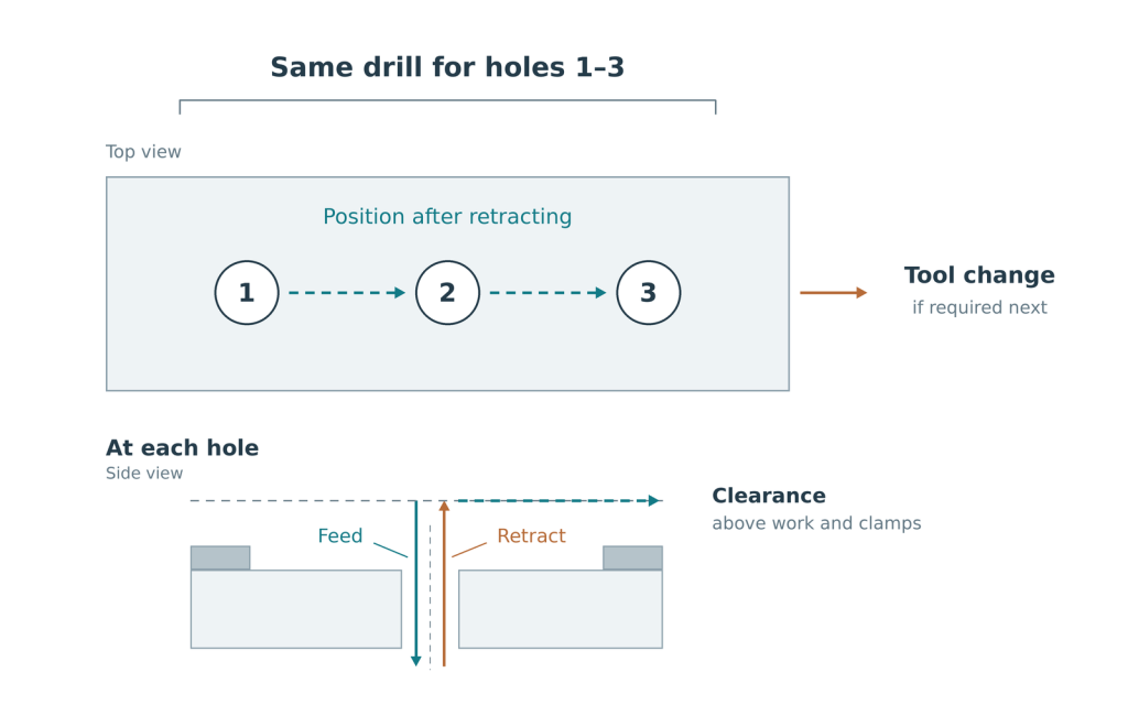
Count the repeated cutting cycles separately. A modest difference per hole can accumulate across a dense pattern and a repeat order. Meanwhile, preparing several drills for a short run may involve work that a suitable existing milling tool avoids. These are different effects, and the supplier’s actual tool list and sequence determine their value.
Ask which preparation is charged once, which operations repeat for each setup or part, and whether required finishing and deburring are included in both proposals. An existing drill still needs appropriate holding, setting and condition checks. An existing end mill still needs a suitable program and a verified route for the proposed holes. Neither option should be treated as having zero preparation simply because the tool is already on the shelf.
For an order with mixed hole groups, request a proposal through RapidEfficient’s CNC milling services that identifies where drilling is retained, where milling is proposed and which later operations remain. Mark any required machining method explicitly. Where the method is open, ask the supplier to return the hole schedule with the proposed operations and the scope for initial and repeat orders.