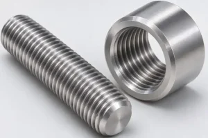

Use a thread size chart to match both nominal diameter and pitch to the mating component. In M8 × 1.25, the numbers mean an 8 mm nominal diameter and a 1.25 mm pitch. In 5/16-18 UNC, they mean a 5/16-inch nominal diameter and 18 threads per inch. Converting the diameters to the same unit helps compare them; the pitch still has to match.
For a replacement CNC bracket, spacer or threaded shaft, the existing mating part usually fixes that interface. The tables below help identify common straight fastening threads and explain why a nearby size can be the wrong purchase. They cover common single-start ISO metric M and Unified UNC/UNF fastening threads, excluding pipe threads, self-tapping screws and special forms.
Common Metric and Unified Thread Sizes
The diameters below are nominal major diameters. On an external thread, the major diameter is measured across the crests. Actual manufacturing limits depend on the specified thread and tolerance class. These values are not tap-drill sizes or finished internal-hole acceptance limits.
Metric Coarse Threads
Metric pitch is the axial distance between corresponding points on adjacent thread forms. These selected diameter–pitch combinations appear in Table 2 of ISO 261:1998.
| Metric size | Nominal major diameter, mm | Coarse pitch, mm | Size written with pitch |
|---|---|---|---|
| M3 | 3 | 0.50 | M3 × 0.5 |
| M4 | 4 | 0.70 | M4 × 0.7 |
| M5 | 5 | 0.80 | M5 × 0.8 |
| M6 | 6 | 1.00 | M6 × 1 |
| M8 | 8 | 1.25 | M8 × 1.25 |
| M10 | 10 | 1.50 | M10 × 1.5 |
| M12 | 12 | 1.75 | M12 × 1.75 |
| M16 | 16 | 2.00 | M16 × 2 |
Fine pitches use the same nominal diameter with smaller spacing. For example, M8 × 1 differs from the coarse M8 × 1.25; M10 × 1.25 differs from M10 × 1.5. Writing the pitch explicitly makes the intended mating combination clear when transferring a specification between a drawing, hardware order and machining order.
Unified UNC and UNF Threads
UNC and UNF identify coarse and fine Unified series. TPI means threads per inch. At a given diameter, the larger TPI value gives the finer pitch.
| Inch size | Nominal major diameter, in. | Converted diameter, mm | UNC, TPI | UNF, TPI |
|---|---|---|---|---|
| #4 | 0.1120 | 2.8448 | 40 | 48 |
| #6 | 0.1380 | 3.5052 | 32 | 40 |
| #8 | 0.1640 | 4.1656 | 32 | 36 |
| #10 | 0.1900 | 4.8260 | 24 | 32 |
| 1/4 | 0.2500 | 6.3500 | 20 | 28 |
| 5/16 | 0.3125 | 7.9375 | 18 | 24 |
| 3/8 | 0.3750 | 9.5250 | 16 | 24 |
| 1/2 | 0.5000 | 12.7000 | 13 | 20 |
The selected inch sizes and thread counts can be checked in Metric & Multistandard Components’ thread identification chart. Millimeter values here are arithmetic conversions using exactly 25.4 mm per inch; their decimal places do not prescribe machining tolerances.
A #8 screw is not an 8 mm screw. The number identifies a nominal 0.164-inch diameter. Likewise, #10-24 and #10-32 share a diameter but have different pitches. Retain the series when recording the designation, such as #10-24 UNC or #10-32 UNF.
Unified thread requirements are covered by ASME B1.1-2024. Apply the standard and edition specified for the order when establishing actual limits. This selected size chart is for identification, not a reproduction of the standard’s tolerance tables.
Why M8 × 1.25 and 5/16-18 Are Not Substitutes
The 5/16-inch nominal diameter converts to 7.9375 mm, only 0.0625 mm below M8’s 8.0000 mm nominal diameter. A rough outside-diameter check can therefore leave both as candidates. Comparing pitch separates them:
Pitch in millimeters = 25.4 ÷ TPI
For 5/16-18 UNC, the pitch is 25.4 ÷ 18 = approximately 1.4111 mm. For M8 × 1.25, it is 1.2500 mm.
Imagine two ideal rows of corresponding thread crests aligned at the first crest. After six pitch intervals, the metric row spans 7.5000 mm, while the Unified row spans approximately 8.4667 mm. Their corresponding seventh crests are about 0.9667 mm apart. The difference grows along the thread rather than disappearing because the diameters are close.
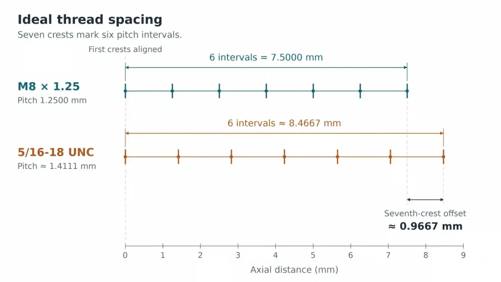
This is a spacing illustration, not a prediction of how many turns two real parts will engage. Chamfers, clearances, damage and deformation affect attempted assembly. Stop if a suspected mismatch binds; forcing it can damage the threads.
The purchasing consequence is direct: a supplier’s proposal to replace an M8 × 1.25 feature with 5/16-18 changes the mating interface. Calling the change an inch conversion would conceal the different pitch. Even within the metric system, replacing M8 × 1.25 with M8 × 1 requires a corresponding change to the mating thread.
Identify an Unmarked Sample Without Guessing the Fit
Start with the component drawing or the hardware manufacturer’s part number when available. When only a sample remains, clean it and examine an undamaged region. Record whether it is an internal or external thread and whether its diameter is straight or tapered. An unfamiliar pipe or special thread belongs outside these tables. Confirm whether the thread is right-hand or left-hand: opposite hands cannot mate, even when diameter and pitch match. Preserve any LH designation and verify the hand on an unmarked sample.
For an external thread, measure across intact crests, away from the entry chamfer and runout. Avoid using the head, an unthreaded shank or a damaged first turn as the diameter reference.
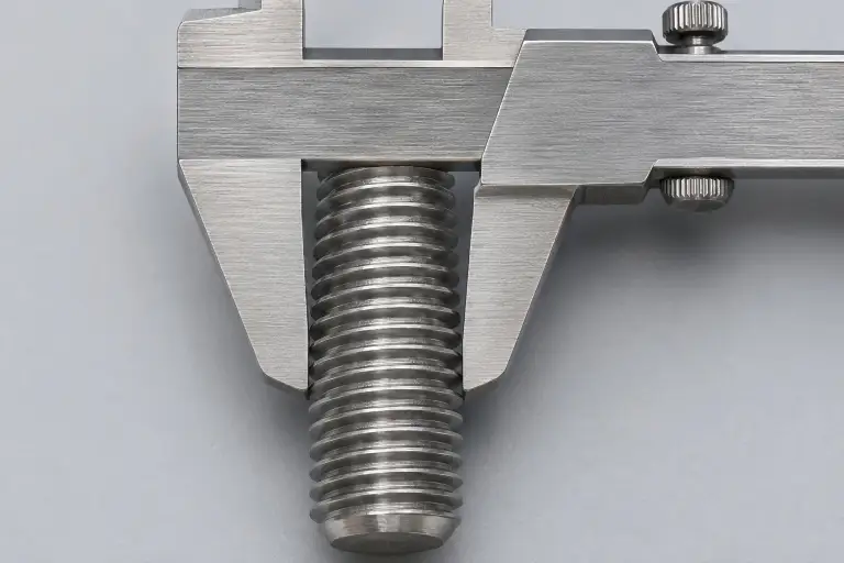
Use a suitable pitch-gauge leaf to compare spacing over several complete threads. Alternatively, where the crests can be resolved reliably, measure an axial span across several pitch intervals and divide by the number of intervals. Eleven consecutive crests contain ten intervals. An illustrative 12.50 mm span across those intervals corresponds to a 1.25 mm pitch. Counting eleven intervals would give the wrong answer.
These checks narrow the candidate designation. Wear, coating and measurement uncertainty still affect the readings, and a pitch-gauge leaf is not a thread acceptance gauge. For an internal thread, the crests define the minor diameter, while the roots define the major diameter. An entry chamfer can also enlarge the opening. Do not identify the nominal size by comparing a mouth measurement directly with the chart’s major-diameter column. Confirm the proposed identification with suitable thread measurement or gauging before specifying production parts from it.
Once the size and pitch are known, assign the required tolerance class separately. In an illustrative M8 × 1.25-6H internal-thread callout, 6H is the tolerance class; it does not change the nominal diameter or pitch. The thread classes guide explains that separate choice and its effect on manufacturing limits.
Keep the Existing Interface or Redesign the Pair
For a replacement part that must fit retained hardware, preserve the verified mating specification. If a supplier quotes another pitch because the tool is available, compare that proposal as a design change. A lower machining price is of little use when the replacement cannot accept the installed screw or shaft.
For a new assembly, the choice can include both sides of the joint. Compare the proposed thread with available mating hardware, suitable tooling and the gauges needed for the specified class. Availability depends on size, material, quantity and location; a “standard” chart entry is not a stock guarantee. A CNC machining review can address the proposed feature and manufacturing route, while the design owner retains responsibility for the joint’s load, engagement and service requirements.
After selecting the pair, keep its designation consistent in the part drawing, hardware specification and purchasing record. Thread depth, entry geometry and any finishing requirements still belong on the relevant documents, but they should all refer to that same selected interface.
If only one side of an existing assembly is being replaced, keep the established thread. If both sides may change, evaluate and approve the pair together, including any effect on spare-part interchangeability. The useful choice is a defined mating system that can be supplied and maintained, rather than the closest diameter in the table.