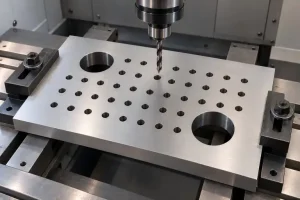

A 1/4-18 NPT port is not a 1/4-inch-diameter hole. The callout identifies a nominal pipe size, 18 threads per inch and a tapered thread form. The diameter changes along the thread, so a caliper reading at the opening cannot establish whether the port meets its specification.
For a purchased machined block or housing, the NPT requirement must work with the mating fitting. The drawing needs enough space for the thread and the fitting’s installed position, while the inspection plan needs the correct gauge reference. Any requirement to supply an assembled, tested connection adds work beyond machining the port.
Read the NPT Callout
NPT is the general-purpose tapered pipe thread covered by ASME B1.20.1. In a designation such as 1/4-18 NPT, the fraction is the nominal pipe size and the second number is the thread count per inch, or TPI. Neither number gives the finished bore diameter or the required drill size.
These common size-and-pitch combinations help read a drawing:
| Nominal pipe size, in. | Threads per inch | Example designation |
|---|---|---|
| 1/8 | 27 | 1/8-27 NPT |
| 1/4 | 18 | 1/4-18 NPT |
| 3/8 | 18 | 3/8-18 NPT |
| 1/2 | 14 | 1/2-14 NPT |
| 3/4 | 14 | 3/4-14 NPT |
| 1 | 11.5 | 1-11.5 NPT |
The table lists designations, not manufacturing limits. Swagelok’s thread and end connection identification guide provides these size-and-pitch relationships and distinguishes identification measurements from acceptance criteria. Use the specified standard and drawing for the actual thread limits.
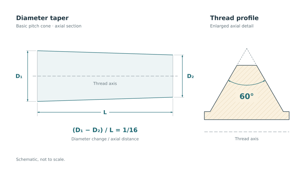
The NPT thread profile has a 60° included angle. Its basic taper is 1:16 on diameter: the corresponding diameter changes by one unit over sixteen units of axial distance. The thread profile angle and the taper describe different geometry.
Confirm the complete connection designation on both components. BSP tapered threads are a different system; a matching nominal size or pitch does not establish compatibility. NPTF is also distinct. Its Dryseal thread form uses controlled crest and root contact, so an NPTF requirement should not be silently replaced with ordinary NPT. Confirm any proposed mixed connection against the fitting manufacturer’s requirements.
Place the Taper Inside the Port
Consider an illustrative block with a female NPT port leading to a cross-drilled passage. The section must accommodate the tapered thread, its incomplete end region, machining clearance and the installed fitting. A model showing a cylindrical hole with a thread label can conceal these relationships.
The taper makes axial position part of the size problem. For the basic cone:
Diameter change = axial distance ÷ 16
For example, sections separated by 0.80 mm along the axis differ by 0.05 mm in corresponding diameter. This is an illustrative geometric calculation, not a port tolerance or a recommended machining adjustment. It explains why changing where the tapered profile sits can change how far a fitting enters.
Do not use a deeper thread simply to make the fitting disappear farther into the block. The resulting thread must still meet its specified limits. Check the fitting’s possible installed positions against the surrounding geometry: its end must not bottom against an internal shoulder, and it must not obstruct a passage that needs to remain open.
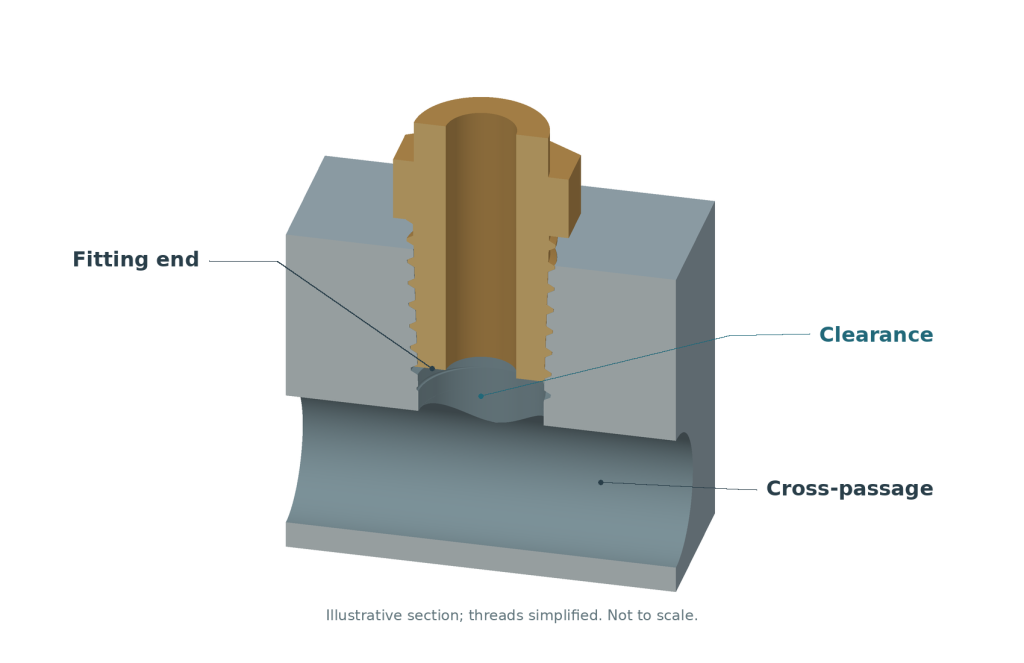
Separate the required usable thread length from the prepared hole depth. Incomplete threads and tool clearance consume space beyond the useful engagement region. If the hole has a closed bottom, retain the required material beneath the machining envelope. The blind-hole depth guide explains the distinction between usable feature depth and the space needed to produce it.
The port section should also show the entry chamfer, any recess and nearby thin walls. These features affect tool access, thread support and the reference used for inspection. Leave the manufacturing route open where appropriate; specifying NPT does not itself require either tapping or thread milling.
For a CNC machining review, provide a section view of the port and the mating fitting drawing or part number. Mark any forbidden breakthrough, internal obstruction and clearance required around the fitting’s wrench flats. That gives the supplier the geometry needed to assess the port within the actual part.
Use the Correct Reference for NPT Gauging
A female NPT thread is commonly checked with a calibrated L1 tapered thread plug gauge at hand-tight engagement. Its marked position is read relative to the applicable part reference. Follow the specified gauging procedure and acceptance limits; forcing the gauge farther in changes the check.
An entry chamfer or counterbore can affect that reference. Do not assume that the gauge mark must always align with the outermost face of the block. Use the reference required by the specified standard for the actual entrance geometry.
Vermont Gage’s NPT inspection guidance explains this reference issue and the limits of the L1 check. L1 gauging does not inspect the full wrench-tight engagement lengths. Conformance still requires the other specified characteristics, including taper, lead and thread form, to be controlled over the required region.
A port-location measurement answers another question: where the thread axis lies relative to the part’s datums. It does not replace thread gauging. Likewise, screwing in one production fitting is an assembly observation, not a substitute for the specified inspection method.
State whether thread acceptance applies before or after finishing. If plating or another coating enters the thread, the process plan must accommodate its effect. A pre-finish gauge result alone does not demonstrate that the delivered thread meets the final requirement.
Specify the Connection That Will Be Tested
Conventional NPT connections rely on suitable thread sealant for pressure-tight service. Select the sealant and assembly method for the fitting, port material, fluid and operating conditions. A coating on the part is not automatically an approved thread sealant.
If an elbow must point in a particular direction, resolve that requirement with the fitting supplier. A standard NPT callout does not specify the elbow’s final orientation. Follow the fitting manufacturer’s assembly procedure. Do not loosen a tightened tapered pipe-thread connection just to obtain the required orientation. Where necessary, review a different connection arrangement as a design change.
Keep the inspection and sealing deliverables explicit. A supplier may quote a finished, inspected port without installing the fitting. If the order includes a leak test, identify the actual fitting, sealant, assembly condition, test medium, pressure, duration and acceptance criterion. State whether the supplier delivers that tested assembly or removes the fitting afterward; reassembly creates a connection that the earlier test did not verify.
The purchase order can then distinguish two concrete deliverables: a machined NPT port that meets its drawing, and, where required, an assembled connection verified under the agreed test conditions.