
An EDM-cut slot can meet its width and roughness requirements while its surface layer remains unverified. If the order requires recast-layer control, a dimensional report and an Ra reading do not close that requirement.
For CNC parts that include EDM features, agree on the controlled surfaces, the permitted layer condition and the evidence needed to accept them. Plan this before machining: a destructive inspection needs a sample, and a removal operation needs access and enough material allowance to preserve the final geometry.
The EDM recast layer is metal that melted during electrical discharge machining and then solidified on the workpiece instead of being removed. Its acceptability depends on the material, the feature’s function and the governing specification. Its presence alone does not make every EDM part defective.
Separate Recast from the Metal Below It
The recast layer, often called the white layer, belongs to the thermally changed surface produced by EDM. Beneath it, material may also have been altered by heat without melting. Removing the resolidified layer therefore does not automatically remove the entire heat-affected region.
The distinction matters when a drawing says only “remove the EDM layer.” Does the requirement concern resolidified material, cracks, a heat-affected zone, or a defined combination? These are different acceptance questions.
Uddeholm’s guide to EDM of tool steel describes changes in the surface layers and their dependence on machining conditions. Its tool-steel guidance should not be treated as a universal description of every alloy or a heat-treatment recipe for every CNC part.
For a hardened insert, the review may concern cracks and altered material near a loaded edge. For another component, the applicable specification may allow an EDM surface with a stated layer limit. Follow the actual functional and contractual requirement rather than adding a blanket removal instruction.
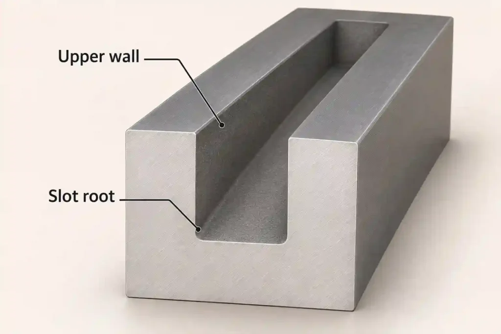
Mark the affected faces on the drawing. A requirement for the walls of a narrow slot should not be left to interpretation as applying only to the accessible top surface.
An Ra Reading Leaves the Layer Unmeasured
Ra describes a surface profile’s roughness under specified measurement conditions. It does not measure the thickness of material that melted and resolidified. A smoother surface can still contain recast material.
Likewise, a CMM report can establish sampled feature geometry without establishing the condition of the metal beneath the surface. Keep these measurements separate when reviewing a supplier’s evidence.
| Evidence supplied | What it addresses | What remains unresolved |
|---|---|---|
| Slot-width or profile report | The measured geometry at the stated production stage | Recast thickness and subsurface condition |
| Ra measurement | Roughness along the measured trace under the stated settings | Whether recast remains below that surface |
| Record of finishing skim cuts | The machining sequence used | The actual remaining layer unless the process has relevant validation |
| Prepared metallographic section | Layer structure and thickness at the examined section | Unsampled locations and other production parts |
| Record of polishing or another removal operation | The treatment performed | Whether the required material was removed everywhere and final geometry was retained |
A requirement expressed as a maximum layer thickness also needs a different result from an average thickness. A thin region can lower an average while a locally thick region remains. If the specification limits the maximum observed thickness, an average-only report cannot demonstrate compliance.
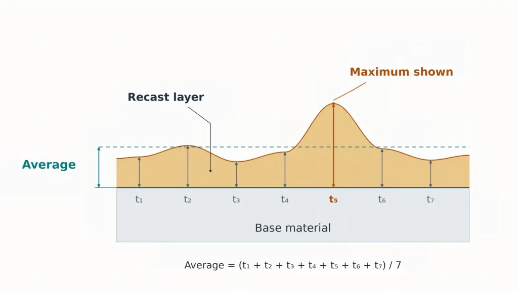
Avoid interpreting “no recast detected” as proof of an infinitely thin or universally absent layer. The statement needs an agreed examination method, suitable detection capability and defined inspection coverage.
Choose the Section Before Cutting the Sample
Metallographic examination involves preparing a section through the surface so that the layer can be examined microscopically. The section location and orientation determine what the examination can reveal.
In a study of EDM-machined Hastelloy C-22, researchers sectioned samples perpendicular to the machined surface, prepared and etched them, and took repeated thickness measurements. They observed uneven and discontinuous recast layers. Those findings illustrate why the sampling plan matters; the study’s measured thicknesses are not acceptance limits for other parts.
Consider a narrow slot in a steel insert. A section near its mouth may show the condition of an upper wall, but it does not establish the condition near the bottom or at a wall-to-floor transition. Those areas may have different machining and subsequent finishing conditions.
Choose locations from the controlled faces and the proposed process. Where the slot root is part of the requirement, the inspection plan should address that region rather than selecting only the easiest place to cut.
A separate witness coupon can preserve a saleable part, but its relevance must be established. Matching the alloy alone is insufficient if the coupon has an open face while the production feature is deep and difficult to flush or finish. Review material condition, EDM settings, geometry, flushing, finishing and the coupon’s relationship to the production batch.
If a coupon cannot represent the feature adequately, a sacrificial part or another agreed verification approach may be needed. Establish that scope before pricing the inspection.
The report should identify the part or coupon, drawing revision, section locations, production stage and examination method. Include images with a scale and the results required by the specification, such as maximum observed thickness, average thickness or crack observations. Specimen preparation must preserve the edge being assessed; damage introduced during preparation should not be mistaken for the production surface.
Check Where the Removal Process Can Reach
Finishing EDM can reduce the affected surface layer. For wire EDM, lower-energy skim cuts are one way to improve the surface after the initial cut. The Complete EDM Handbook’s discussion of recast and heat-affected zones explains the influence of power supply and skim cuts.
A specified number of passes is a process instruction, however. It becomes evidence of a layer condition only when supported by validation relevant to the material, geometry and machining conditions. Do not assume that the same pass count produces the same result on every part.
When additional removal is required, examine the actual tool or treatment access. Grinding or controlled polishing may suit an exposed face. A narrow internal slot presents a different problem: reaching its walls, floor and transitions without changing the required shape.
A polishing tool that reaches the slot mouth may not reach the root. Increasing tool access by enlarging the slot or rounding an internal corner changes the part and requires design approval.
Chemical or electrochemical removal also needs a process suitable for the alloy and geometry. The ability of a liquid to enter a recess does not establish uniform removal or dimensional compliance. Review the intended treatment with the processor and require evidence for the specified surface condition.
If the required surfaces cannot be reached or verified, resolve that issue before approving the EDM route. An accessible alternative feature, a different manufacturing sequence or a qualified process may change the decision.
Accept the Surface and Geometry in the Same Final State
Surface removal changes dimensions. Removing material from opposing slot walls widens the slot; removing material from an external tongue narrows it. Local polishing can also change corner radii, edge shape and the relationship between adjacent faces.
The required removal cannot be chosen from a generic recast-thickness value. It must suit the actual surface condition and the validated process, with sufficient allowance for the final feature requirements.
A width report taken before polishing cannot establish the delivered width afterward. Similarly, a section examined before the final EDM pass or removal treatment describes an earlier condition. Identify the production stage represented by each result.
Our EDM machining tolerance guide covers the broader dimensional risks. For a recast-controlled feature, the acceptance plan must connect the layer evidence with the geometry after all specified finishing.
Compare quotations on that same basis. Destructive specimens, section preparation, microscopy, controlled removal and dimensional reinspection are separate work items. Confirm which are included and how the results will remain traceable to the delivered parts. Our quality assurance overview explains the wider inspection and documentation scope.
For a CNC part with a recast-controlled EDM feature, send the marked surface requirements, material condition, governing specification and any required sampling or removal procedure with the drawing. Through our CNC machining services, Rapid Efficient can review the proposed route and coordinate the required finishing and inspection scope with its supplier network. Specialist testing and process acceptance should be confirmed for the project before quotation.