
A cast housing can have a machined mounting face beside an outer wall that must remain unmachined. Surface finish symbols let the drawing assign those different instructions to the same part. Reading only the roughness number can erase a manufacturing restriction that the designer deliberately included.
Read each callout as a combination of its governing standard, the surface it identifies, its material-removal instruction and its additional requirements. A roughness limit, a direction of surface texture and a named finishing process each control a different part of the manufacturing decision.
This article follows ISO profile surface-texture indications and explains why older ISO drawings need separate attention. For a drawing governed by ASME or a customer-specific convention, use that stated system rather than transferring an ISO symbol layout into it.
First Identify Which Symbol System You Are Reading
ISO 21920-1:2021 replaced ISO 1302:2002 for the indication of profile surface texture. The ISO standard record identifies that replacement and the scope of the current document. Start with the drawing’s referenced standards, revision and general notes, then examine the local callout.
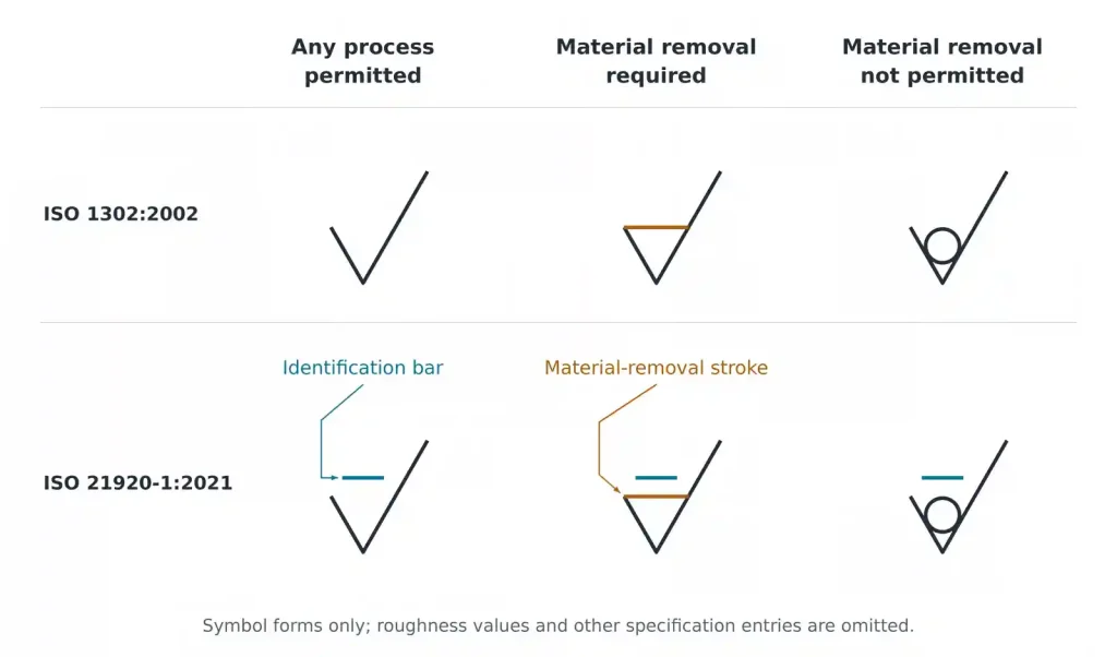
The newer ISO symbols include a separate bar above the root symbol to identify the ISO 21920 system. That identification bar is distinct from the stroke that indicates required material removal. The shortcut “a bar means machining” is therefore unsafe unless the reader has identified which bar and which symbol system are present.
Older dated drawings can retain their requirements under the earlier system. Mahr’s explanation of the standards change discusses both the changed symbols and the continuing validity of older drawings. If a drawing mixes a legacy symbol with a conflicting standard note, ask the drawing owner to resolve the interpretation before programming the surface.
Within the correct symbol family, distinguish three manufacturing instructions:
| Symbol variant | Manufacturing instruction | Consequence for the proposed route |
|---|---|---|
| Any-process variant | Any manufacturing process is permitted by this part of the callout | Choose a route that also meets the remaining drawing requirements |
| Material-removal variant | Material must be removed | A suitable cutting or other removal operation is required; the symbol alone does not select grinding |
| No-material-removal variant, with a circle in the root symbol | Material removal is prohibited on the indicated surface | Do not add a cleanup cut or abrasive polishing to that surface without an approved change |
These are instructions for the surface identified by the callout. A no-removal indication on a casting wall does not prevent machining a separate mounting boss. Follow the leader or surface association, including any stated extent, instead of applying one local symbol to the entire component.
The required-removal symbol also carries no numerical stock allowance by itself. It cannot tell the programmer how much material is available between the incoming blank and the finished surface. That information comes from the part geometry and the specified blank or intermediate condition.
Read the Texture and Process Entries Separately
After identifying the symbol, read the parameter and its limit together. Ra 0.8 and Rz 0.8 specify different characteristics despite sharing the same number. The Ra and Rz comparison explains that parameter choice; here, the task is to preserve the requirement while translating the drawing into operations.
Keep the roughness unit attached to the value. A metric part dimension does not justify guessing the unit on an imported legacy finish note. For a unit conversion, 32 microinches equals 0.8128 micrometers. That conversion does not change the parameter or authorize rounding a specification limit to 0.8 micrometers. Resolve an ambiguous number from the drawing’s stated convention.
The lay entry describes the direction of the surface pattern. C indicates an approximately circular lay, R a radial lay, and M a multidirectional lay. ZEISS’s surface-parameter reference illustrates these entries alongside the process symbols and specification fields.
On an annular face, circular marks run around the center; radial marks run toward or away from it. A proposal to substitute one pattern for the other changes a specified surface characteristic, even if the reported Ra remains the same. The lay designation describes the surface. A direction specified for acquiring a measurement profile is a separate instruction.
A named process adds another constraint. If the applicable note requires grinding, offering turning to the same Ra is a proposed process change. Conversely, a material-removal symbol accompanied by a roughness requirement does not automatically require grinding when no such process restriction is present.
Read process words in context. A note may govern one face, a group of faces or a particular manufacturing stage. Copying only “Ra 0.8” into the machining plan can lose a nearby process requirement that still applies to the delivered part.
Unfilled fields can have defined defaults. Under ISO 21920, omitted specification details are handled through the applicable default rules; Mahr describes this role of Part 3 and the default maximum-value acceptance rule. The drawing and governing standard therefore travel together. A blank field is not permission to choose whichever filter or evaluation setting produces a favorable result.
Compare Two Routes for the Same Housing
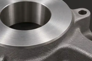
Consider a hypothetical cast housing with an annular mounting face around a bore. Its drawing requires material removal on that face, an upper Ra limit of 0.8 micrometers and circular lay. A separate no-material-removal indication applies to an adjacent outer wall. These are teaching requirements, not recommended values for every mounting or sealing face.
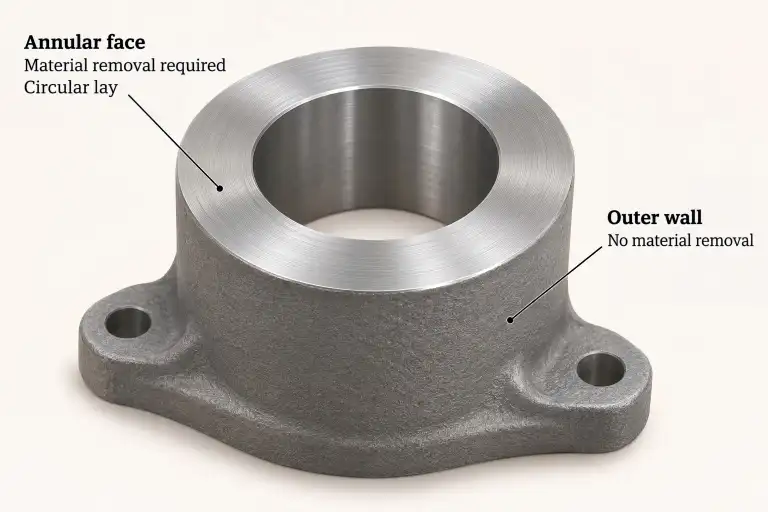
The first proposal turns the annular face and leaves the outer wall untouched. Turning is a candidate for the face because its cutting motion can produce approximately circular marks. The supplier still has to demonstrate the specified texture on the actual material and geometry. The drawing’s dimensions and geometric tolerances continue to govern the face and bore.
The second proposal mills the annular face, then polishes it until an Ra reading falls below 0.8 micrometers. That description leaves the circular-lay requirement unresolved. Polishing can change the surface pattern, so the finished pattern must be assessed rather than inferred from the preceding milling operation or the roughness result.
Milling is not categorically excluded by a circular-lay requirement. A proposed toolpath and finishing sequence must produce the required surface. The distinction is between a demonstrated result and an assumption based on the process name.
Now suppose either proposal includes skimming the adjacent casting wall to improve its appearance or create a convenient locating pad. That operation conflicts with the no-removal instruction on that wall. A fixture may need another locating strategy. If the design needs a machined pad, its position and dimensions belong in an approved drawing change before the cut is made.
There is a further distinction if the annular face carries an explicit grinding requirement. A turning proposal would then need approval as a process substitution, even if its texture measurements were satisfactory. The original material-removal indication and the additional process note must both be honored.
For this housing, a useful CNC machining review compares the proposed operations face by face: how the annulus obtains its specified lay, how the outer wall remains uncut, and whether any named process is being replaced. Keep a requested change attached to the exact face and instruction it would alter. Approval of a roughness result should not silently approve removal from another surface or waive a specified process.