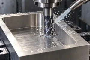
Quick Answer: What Are the Three Types of Metal Bending?
A practical way to group common metal bending methods is:
- Air bending
- Bottom bending
- Roll bending
Air bending and bottom bending are press-brake processes used mainly to create straight bends and flanges in sheet or plate.
Roll bending uses three or four rolls to form large radii, cylinders, cones, and curved sections.
This is not the only possible classification. In press-brake terminology, coining, hemming, folding, and panel bending may also be treated as separate processes. Bottom bending and coining should not be treated as the same method.
The correct process depends on the material, thickness, temper, bend length, inside radius, angle tolerance, surface requirement, production quantity, and available machine capacity.
TRUMPF separately defines air bending, bottom bending, folding and hemming, while plate-roll manufacturers provide both three-roll and four-roll systems. Therefore, the original article’s three-method grouping is useful for buyers, but it should not be presented as the only universal classification.
Why Use Metal Bending?
Metal bending can create brackets, channels, covers, enclosures, frames, cylinders, and curved sections while retaining most of the original material.
Its main advantages may include:
- Efficient use of sheet, plate, tube, or profile material
- Repeatable bend angles when material and tooling are controlled
- Fewer welded joints for suitable one-piece designs
- Practical production of flanges, channels, and enclosed shapes
- Flexibility from prototypes to repeat production
- Compatibility with cutting, welding, machining, and surface finishing
- Good structural efficiency when the bend radius and part geometry are designed correctly
These benefits are not automatic.
Final accuracy, appearance, and cost still depend on:
- Material grade and temper
- Thickness variation
- Grain direction
- Inside bend radius
- Springback
- Bend length
- Punch and die condition
- Machine capacity
- Hole and edge locations
- Cosmetic-surface protection
- Production quantity
Bending may cause local work hardening, but it can also introduce residual stress, cracking, surface marking, or distortion. The process should therefore be selected from the finished-part requirements rather than from a general claim that bending always makes a component stronger or cheaper.
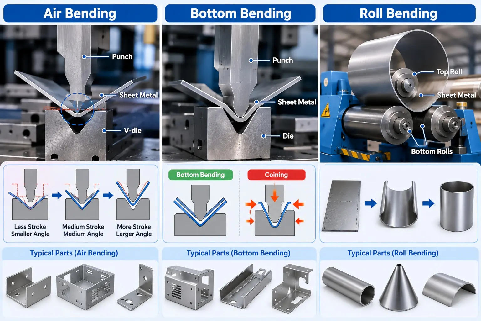
Air Bending vs Bottom Bending vs Roll Bending
| Comparison Item | Air Bending | Bottom Bending | Roll Bending |
|---|---|---|---|
| Main equipment | Press brake with punch and V-die | Press brake with closely matched punch and die | Three-roll or four-roll bending machine |
| Typical shape | Straight flanges, channels, brackets, boxes, and angled parts | Repeated straight bends with controlled tool geometry | Cylinders, cones, arcs, tanks, and large-radius sections |
| How the angle is formed | Punch depth controls the angle without fully seating the sheet in the die | Sheet is pressed more completely into matched tooling | Material passes through adjustable rolls to form curvature |
| Tool flexibility | One tool set can produce several angles within its usable range | More dependent on the selected punch-and-die geometry | Roll position determines the radius and curvature |
| Required force | Generally lower than bottoming or coining | Higher than air bending | Depends on thickness, width, material, radius, and roll arrangement |
| Springback sensitivity | Usually requires greater springback compensation | Generally lower springback than air bending | Radius may relax after unloading and require compensation |
| Main advantage | Flexible, efficient, and suitable for many sheet-metal parts | Repeatable angle formation when material and tooling are controlled | Produces continuous curves and cylindrical shapes |
| Main limitation | Sensitive to material thickness, strength, grain direction, and springback | Higher force and less tooling flexibility | Straight ends, pre-bending, roundness, and seam alignment require planning |
| Best starting point | Mixed angles, prototypes, low volume, and general sheet-metal fabrication | Stable repeat work with controlled material and dedicated tooling | Large-radius and cylindrical components |
Air bending is normally the most flexible of the three because the punch stroke controls the angle and one punch-and-die combination can produce multiple angles. LVD also notes that it generally requires less force than other press-brake techniques.
1. Air Bending
Air bending is a press-brake process in which the sheet contacts the punch tip and the upper edges of the die opening without being fully pressed against the bottom of the die.
The punch moves into the die opening, and the programmed punch depth controls the final bend angle.
Advantages of Air Bending
Air bending is widely used because it provides:
- Flexible angle adjustment
- Lower forming force than bottom bending or coining
- Fewer tool changes for different angles
- Practical processing of prototypes and mixed batches
- Compatibility with CNC angle correction and measurement systems
- Lower tooling investment for varied part designs
One punch-and-die combination may produce several angles, provided the required radius, flange length, material, and machine capacity remain within the tool’s operating range.
Main Engineering Risks
Air bending is more sensitive to material variation than the original article suggests.
The final angle may change with:
- Sheet thickness
- Material strength
- Temper
- Grain direction
- Tool wear
- V-die opening
- Punch radius
- Punch depth
- Springback
- Bend length
Air bending does not automatically prevent over-bending. The process often intentionally bends beyond the target angle to compensate for springback.
Modern angle-measurement systems can correct the ram position during bending, but the drawing and material specification still need to be clear.
Typical Applications
Air bending is commonly used for:
- Brackets
- Channels
- Enclosures
- Equipment covers
- Mounting plates
- Electrical cabinets
- Sheet-metal housings
- Prototype and low-volume fabricated parts
- Components containing several different bend angles
TRUMPF describes air bending as a path-dependent method in which punch depth determines the angle, while LVD notes that material thickness, strain hardening, and grain direction can all change the bend result.
2. Bottom Bending
Bottom bending, also called bottoming, is a press-brake process in which the sheet is pressed more completely into the die than it is during air bending.
The punch, sheet, and die geometry work together to control the bend. The tooling must therefore match the required angle and form more closely.
Bottom Bending Is Not the Same as Coining
Bottom bending and coining are sometimes incorrectly treated as interchangeable.
In bottom bending, the sheet is seated against the die and the punch depth helps determine the bend angle.
Coining applies substantially greater pressure and forces the material into closer contact with both the punch and die surfaces. It is a separate forming method rather than another name for ordinary bottom bending.
Advantages of Bottom Bending
Bottom bending may provide:
- Lower springback than air bending
- Stable bend angles with controlled material
- Good repeatability for dedicated production
- Clear tool-defined geometry
- Reduced dependence on punch-depth adjustment after setup
Main Engineering Risks
Bottom bending requires more force and is less flexible than air bending.
The supplier should confirm:
- Material grade and temper
- Sheet-thickness tolerance
- Bend length
- Punch angle
- Die angle
- Inside radius
- Press-brake tonnage
- Tool load capacity
- Surface-marking requirements
- Production quantity
Bottom bending should not automatically be described as the best method for thicker materials. Thick or high-strength plate may exceed the available machine or tooling capacity, and roll bending or another forming route may be more suitable.
Typical Applications
Bottom bending may be useful for:
- Repeated brackets
- Channels
- Covers
- Enclosures
- Parts with stable material and thickness
- Production runs using dedicated tooling
- Components requiring repeatable straight bends
TRUMPF states that bottom bending uses matched tooling and higher pressure to stabilize the angle, while LVD distinguishes bottoming from coining and notes that bottoming is commonly applied where material properties and thickness are consistent.
3. Roll Bending
Roll bending forms metal into a continuous curve by passing the material through adjustable rolls.
The original article describes only a three-roll machine, but both three-roll and four-roll machines are widely used.
Possible configurations include:
- Three-roll initial-pinch machines
- Three-roll double-pinch machines
- Three-roll variable-axis machines
- Four-roll plate-bending machines
- Section or profile bending rolls
Advantages of Roll Bending
Roll bending is suitable for:
- Large radii
- Cylinders
- Cones
- Curved panels
- Tanks
- Shells
- Rings
- Structural profiles
The roll positions can be adjusted to change the radius, and some machines support CNC-controlled repeat production.
Four-roll machines can clamp and control the plate during forming, while three-roll machines may be practical for flexible or lower-volume production.
Main Engineering Risks
Roll bending does not automatically produce a complete cylinder without further planning.
Important issues include:
- Straight sections near the plate ends
- Edge pre-bending
- Roundness
- Cone alignment
- Material springback
- Plate thickness variation
- Weld-seam preparation
- Surface marking
- Roll deflection
- Final diameter after welding
- Removal of a closed cylinder from the machine
The buyer should state whether the required dimension is:
- Inside radius
- Outside radius
- Centerline radius
- Inside diameter
- Outside diameter
- Diameter before welding
- Diameter after welding
Typical Applications
Roll bending is commonly used for:
- Tanks
- Cylindrical shells
- Ducts
- Curved covers
- Conical sections
- Large-radius panels
- Pipe and structural sections
- Industrial equipment components
DAVI manufactures both three-roll and four-roll plate-bending systems. Its four-roll design uses the bottom roll to clamp the plate during forming, while three-roll designs use different movable-roll arrangements for edge pre-bending and plate rolling.
How to Choose the Right Metal Bending Method
| Project Requirement | Recommended Starting Point | Why |
|---|---|---|
| Several different straight bend angles | Air bending | One tooling setup may produce multiple angles |
| Prototype or low-volume sheet-metal part | Air bending | Flexible setup and lower tooling commitment |
| Repeated straight bend with controlled material | Bottom bending | Dedicated tooling can improve angle repeatability |
| Very low springback requirement | Bottom bending or another controlled forming method | Greater tool contact reduces springback sensitivity |
| Cylinder or curved shell | Roll bending | Produces continuous curvature rather than a straight fold |
| Large-radius curved panel | Roll bending | Better suited to gradual curvature |
| Cosmetic sheet with strict surface requirements | Process depends on shape | Tool condition, protective film, bend direction, and contact pressure must be reviewed |
| Thick or high-strength plate | Capacity review required | Machine tonnage, tool load, width, radius, and material strength must be checked |
| Many small flanges and box shapes | Air bending or panel bending | Part handling and bend sequence may control the best method |
| High-volume repeat production | Process depends on geometry | Dedicated tooling, automated angle control, panel bending, or four-roll automation may be justified |
The correct method cannot be selected from part thickness alone. Shape, angle, radius, bend length, quantity, finish, machine capacity, and dimensional requirements must be considered together.
Springback, Bend Radius, and Surface Risks
Springback
After the forming force is removed, the material may partially return toward its original shape. This is called springback.
Springback can change with:
- Material grade
- Yield strength
- Temper or heat treatment
- Sheet thickness
- Grain direction
- Inside bend radius
- Tool opening
- Bending method
- Production batch
A bend program developed for one material lot should not automatically be assumed correct for another thickness, temper, or supplier.
Inside Bend Radius
The drawing should clearly define the required inside bend radius.
A radius that is too small for the material and condition may increase the risk of:
- Cracking
- Surface tearing
- Excessive thinning
- Distortion
- Unstable angle correction
A larger radius may improve formability but can affect flange location, overall size, bend allowance, and assembly fit.
Surface Marks
Bending tools can leave:
- Die lines
- Scratches
- Pressure marks
- Protective-film impressions
- Roller marks
- Polished or coated surface damage
Cosmetic surfaces should be marked on the drawing. Protective film, bending foil, polished tooling, larger contact radii, or another forming route may be required.
LVD’s tooling documentation specifically discusses reducing friction and tooling marks, while TRUMPF’s operating documentation describes bending foil as a way to protect the workpiece from impressions.
RFQ Information for Metal Bending Parts
| RFQ Item | What to Specify | Why It Matters |
|---|---|---|
| Material | Exact alloy or grade | Controls strength, formability, springback, and cracking risk |
| Material condition | Temper, hardness, heat treatment, or delivery condition | The same alloy can bend differently in different conditions |
| Thickness | Nominal thickness and applicable tolerance | Affects angle, force, radius, and tool selection |
| Stock form | Sheet, plate, tube, extrusion, or profile | Determines the suitable bending equipment |
| Bend angle | Final angle and tolerance | Helps select tooling and compensation |
| Bend radius | Inside, outside, or centerline radius | Prevents interpretation disputes |
| Bend length | Length of each bend | Required for force and machine-capacity review |
| Flange dimensions | Minimum flange length and critical edges | Determines tool and backgauge access |
| Grain direction | Bend parallel or perpendicular to rolling direction when relevant | Can affect cracking and angle behavior |
| Surface requirement | Cosmetic side, protective film, acceptable tool marks, or coating | Controls handling and tooling protection |
| Quantity | Prototype and expected repeat volume | Affects tooling and automation decisions |
| Inspection | Angle, radius, profile, hole position, flatness, or template inspection | Defines acceptance before production |
| Post-processing | Welding, machining, deburring, anodizing, plating, painting, or powder coating | Bending can affect later dimensions and appearance |
For custom brackets, channels, covers, enclosures, curved panels, and other formed components, review our metal bending services.
For projects combining cutting, bending, forming, welding, and finishing, review our sheet metal processing services.
Rapid Efficient can review the drawing, material, thickness, bend angle, radius, surface requirements, quantity, inspection points, and post-processing requirements before quotation.
FAQ: Types of Metal Bending
What Are the Three Main Types of Metal Bending?
A practical general classification is air bending, bottom bending, and roll bending.
Air and bottom bending use press brakes for straight bends, while roll bending uses adjustable rolls to produce continuous curves.
Other classifications may also include coining, folding, hemming, panel bending, tube bending, and profile bending.
What Is the Difference Between Air Bending and Bottom Bending?
In air bending, the sheet is not completely seated in the die, and punch depth controls the angle.
In bottom bending, the material is pressed more completely into matched tooling. Bottom bending normally requires more force and provides less tooling flexibility, but it can reduce springback under controlled conditions.
Is Bottom Bending the Same as Coining?
No.
Coining applies substantially greater pressure and forces the material into closer contact with both the punch and die surfaces. Bottoming and coining should be treated as separate processes.
Does Air Bending Require Less Force?
Generally, yes.
Because the sheet is not forced fully into the die, air bending normally requires less force than bottom bending or coining. The actual tonnage still depends on material, thickness, bend length, tool opening, and strength.
Can Roll Bending Produce a Complete Cylinder?
Yes, but edge pre-bending, straight ends, roundness, welding allowance, springback, and part removal must be planned.
The required diameter should be clearly defined as inside, outside, or centerline diameter.
Which Bending Method Has the Least Springback?
Bottom bending generally produces less springback than air bending, but no method eliminates every material and thickness variation.
Tooling, pressure, material condition, grain direction, and angle-control systems still matter.
Does Metal Thickness Determine the Bending Method?
Thickness is important, but it is not the only factor.
The supplier must also check material strength, bend length, radius, angle, machine capacity, tooling, shape, surface requirements, and production quantity.
What Information Is Needed for a Metal Bending Quote?
Provide a 2D drawing or usable 3D model, exact material and condition, thickness, bend angles, inside radii, bend lengths, quantity, cosmetic surfaces, post-processing, inspection requirements, and target delivery date.
Conclusion
Air bending, bottom bending, and roll bending solve different forming problems.
Air bending is the most flexible starting point for many straight sheet-metal bends and mixed production quantities.
Bottom bending uses more complete tool contact to provide stable, repeated bends when the material and tooling are controlled.
Roll bending is used for continuous curves, large radii, cylinders, cones, and curved sections.
The correct choice depends on:
- Material grade
- Temper or hardness
- Thickness
- Bend angle
- Inside radius
- Bend length
- Springback
- Surface requirements
- Machine and tooling capacity
- Quantity
- Inspection method
- Post-processing
The method should be selected from the finished-part requirements, not from a general statement that one bending process is always more accurate or better.
Review Your Metal Bending Project
Send the STEP file, 2D drawing, material, thickness, bend angles, inside radii, quantity, cosmetic surfaces, post-processing, and inspection requirements.
Rapid Efficient can review the bending route, material risks, tooling access, springback, surface protection, inspection points, and related sheet-metal processes before quotation.
For finish requirements after bending, review our surface finishes for metal parts.
For drawing review, inspection planning, and shipment checks, review our quality assurance process.