A PEEK part can pass inspection and still become a problem later.
The bore measures correctly.
The flatness looks acceptable.
The threads fit.
The surface is deburred.
Then the part is unclamped, cleaned, left overnight, packed, shipped, or measured again by the customer.
Now the bore is slightly different. A thin wall has opened. A flat plate has a small bow. A sealing face no longer sits the same way.
That is the real challenge in machining PEEK parts.
The customer is not only asking whether PEEK can be machined.
They are asking:
Why did the PEEK part pass inspection, then move?
PEEK is strong for a polymer. It offers useful heat resistance, chemical resistance, wear behavior, and dimensional capability when the process is controlled.
But PEEK is still a high-performance plastic, not aluminum, brass, or stainless steel.
A metal part usually asks the shop:
Can the machine cut this tolerance?
A PEEK part asks something more difficult:
Will the part still measure correctly after unclamping, stress release, cleaning, resting, finishing, packaging, and real use?
Rapid Efficient supports custom CNC machining projects for engineering plastic parts, including PEEK components for prototypes, low-volume production, and functional assemblies. Before quotation, we review the drawing together with the PEEK grade, part geometry, tolerance notes, thin-wall areas, threaded features, surface finish, inspection method, packaging needs, and delivery schedule.
For broader material selection across metals and engineering plastics, review our CNC machining materials guide.
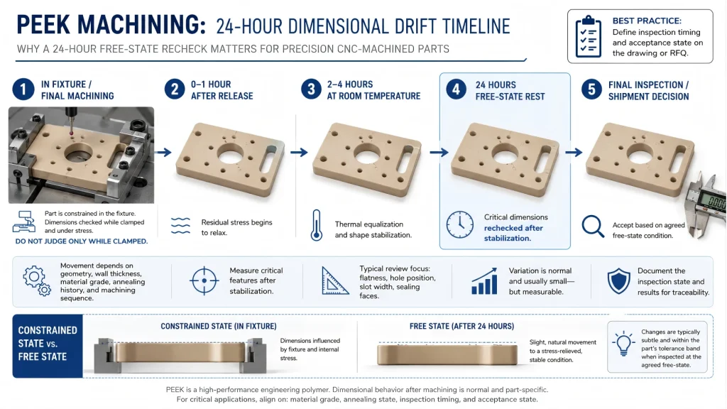
The 24-Hour PEEK Tolerance Drift Timeline
PEEK tolerance problems often happen in stages.
The part does not always fail immediately.
It may move little by little as clamping force, cutting heat, material stress, and inspection condition change.
| Stage | What May Happen | What It Looks Like | Control Method |
|---|---|---|---|
| During clamping | The stock is forced into a temporary shape | Part measures well while restrained | Use softer support and avoid over-clamping |
| During roughing | Internal stress starts to release | Part begins to bow or twist | Rough with allowance and remove material evenly |
| During finishing | Local heat affects the cut zone | Bore, wall, or edge shifts slightly | Use sharp tools and controlled chip load |
| After unclamping | The part returns toward its free-state shape | Thin walls open or flatness changes | Inspect after release, not only in fixture |
| After resting | Dimension stabilizes slowly | Overnight size difference appears | Allow stabilization before final inspection when needed |
| After deburring | Functional edges change | Fit, sealing, or thread start changes | Remove burrs without rounding critical edges |
| After cleaning | Moisture, solvent, or handling affects the part | Surface or fit changes slightly | Define cleaning method and drying condition |
| During packing | Thin features are unsupported | Part arrives with bow or pressure marks | Support fragile features during packaging |
| After shipment | Temperature and handling history differ | Customer measures a different condition | Define inspection condition clearly |
| During assembly | The real constraint appears | Free-state part behaves differently in assembly | Match inspection setup to functional setup |
This timeline is the core of PEEK machining.
The question is not only whether the supplier can hit the number once.
The question is whether the part remains stable when the manufacturing condition changes.
PEEK Grade Changes the Machining Risk
A drawing that says only “PEEK” may not be specific enough.
Different PEEK grades can behave differently during machining, deburring, inspection, and assembly.
Common PEEK material choices include:
| PEEK Type | Why It Is Used | Machining Risk to Review |
| Virgin PEEK | General high-performance plastic applications | Heat, burrs, stress release, tolerance drift |
| Glass-filled PEEK | Higher stiffness and dimensional stability | Increased tool wear, possible edge chipping |
| Carbon-filled PEEK | Wear resistance, stiffness, lower thermal expansion | More abrasive cutting behavior and surface finish control |
| Bearing-grade PEEK | Sliding or wear applications | Surface finish, friction behavior, and mating surface review |
| Medical or semiconductor-grade PEEK | Cleanliness, traceability, or special application needs | Handling, contamination, documentation, and packaging control |
Filled PEEK grades may improve stiffness or reduce movement in some applications, but they can also increase tool wear, edge chipping risk, and surface finish sensitivity.
That is why the RFQ should confirm the exact grade.
A supplier should not quote “PEEK machining” as if every PEEK grade cuts the same way.
The correct question is:
Which PEEK grade is required, and which features must remain stable after machining?
Four Places Where the Movement Comes From
Most PEEK tolerance drift comes from four sources.
Not every part has all four, but precision PEEK parts usually involve more than one.
1. Stock Stress
PEEK stock may already contain internal stress before machining.
When material is removed, the stress balance changes.
If one side is cut heavily and the other side remains thick, the part may bend toward a new shape.
This is common in:
- Plates
- Long rails
- Thin covers
- Large pockets
- Asymmetric parts
- Parts with one heavily machined side
A drawing with a tight flatness callout should not be quoted like a simple block if most of the material must be removed from one side.
2. Clamping Stress
PEEK can deform under holding pressure.
If a soft or thin part is clamped too aggressively, the machine cuts the clamped shape instead of the real shape.
The part looks good until it is released.
Then the wall opens, the slot shifts, or the datum face no longer contacts the same way.
The key question is:
Are we machining the part, or are we machining the fixture-forced version of the part?
For design-level feature planning, wall thickness, holes, slots, and manufacturability review, see our CNC machining design guide.
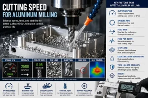
3. Cutting Heat
PEEK can tolerate higher service temperatures than many common plastics, but machining heat is still dangerous.
Heat at the cutting zone can cause smearing, fuzzy burrs, bore change, thread roughness, or local distortion.
This is most likely near:
- Small holes
- Internal threads
- Deep pockets
- Thin walls
- Long slots
- Sealing faces
- Sharp internal corners
- Precision bores
A dull tool is especially risky.
If the edge rubs instead of shearing, the polymer does not just cut. It warms, smears, and moves.
4. Inspection Condition
A PEEK part can measure differently depending on how and when it is inspected.
Important questions include:
- Is the part measured immediately after machining?
- Is it measured after resting?
- Is it measured free-state or restrained?
- Is the inspection temperature controlled?
- Is the part supported the same way it will be supported in assembly?
- Are thin features allowed to relax before final inspection?
For PEEK, inspection is not only a measurement step.
It is part of the process definition.
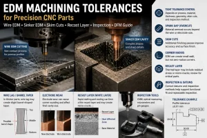
For tolerance planning and measurement boundaries, see our CNC machining tolerances guide.
Thin Walls and Flat Plates Fail First
When machining PEEK parts, thin geometry exposes process weakness quickly.
A thick spacer may remain stable.
A thin plate with pockets may not.
A compact bushing may hold size.
A wide cover with asymmetric cutouts may bow after release.
The highest-risk PEEK geometries include:
- Thin walls
- Large flat plates
- Deep pockets
- Long slots
- Wide covers
- Large material removal from one side
- Thin-bottom pockets
- Press-fit bores
- Sealing faces
- Thin bridges between holes
- Long unsupported rails
These features fail first because they do not have enough stiffness to resist stress release, heat, or fixture pressure.
The part may not look defective.
It may simply be slightly different from the drawing when measured in the real condition.
That is often enough to cause assembly problems.
The Stable PEEK Process Route
For simple PEEK parts, direct machining may be enough.
For precision PEEK components, the process route should be planned before cutting starts.
A stable route may look like this:
- Confirm the PEEK grade and stock condition.
- Identify thin walls, flatness zones, bores, threads, and sealing faces.
- Rough machine with allowance.
- Avoid removing too much material from one side at once.
- Release or relax the part when geometry is sensitive.
- Re-fixture with lower stress.
- Finish critical features after the part has moved.
- Deburr without rounding functional edges.
- Inspect after stabilization when required.
- Pack the part so thin areas are supported.
Not every PEEK part needs this full route.
But the logic matters.
The roughing stage should expose movement before final finishing, not after final inspection.
The finishing stage should cut the part in its more stable condition.
The final inspection should match the condition that matters to assembly.
For high-precision PEEK parts, annealing or stress-relief history should be discussed before quotation. Some stock may already be stress relieved, while selected parts may require stress-relief planning after roughing, after heavy material removal, or before final inspection. This can affect lead time, cost, and inspection timing.
The drawing should clarify whether final dimensions apply after machining, after stabilization, or after stress relief.
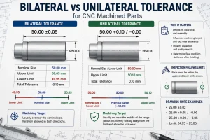
What Buyers Should Mark on the Drawing
A PEEK drawing should not rely only on a general tolerance block.
The supplier needs to know which features truly control function.
Useful drawing notes include:
| Feature or Requirement | Better Drawing Note |
| Thin wall | “Avoid over-clamping; inspect wall thickness after release.” |
| Flat plate | “Flatness measured in free-state condition.” |
| Sealing face | “Do not round or polish sealing edge.” |
| Precision bore | “Bore controls assembly fit; final inspection after stabilization.” |
| Threaded hole | “Thread fit required after deburring and cleaning.” |
| Cosmetic surface | “Protect visible surface from scratches and handling marks.” |
| Insert area | “Confirm insert method and surrounding wall thickness before machining.” |
| Large pocket | “Rough with allowance before finishing critical features.” |
| High-temperature use | “Confirm material grade and inspection condition for service temperature.” |
| Thin feature during packing | “Support part during packaging to prevent deformation.” |
| Stress-relieved requirement | “Final dimensions apply after stress relief.” |
These notes are more useful than marking every dimension tight.
If every feature is critical, the quotation becomes expensive and unclear.
If no feature is identified as critical, the real assembly risk may be missed.
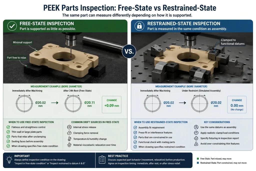
Free-State or Restrained-State Inspection?
This is one of the most important questions for PEEK parts.
Should the part be measured in its free state?
Or should it be measured as installed?
There is no single answer.
A thin PEEK cover may bow slightly when free, but sit correctly when screwed into an assembly.
A sealing component may need to be flat before assembly because the mating surface cannot correct it.
A bushing may need bore size checked in free state, unless the assembly compresses it during installation.
A long rail may need support during measurement if the real assembly supports it in the same way.
The drawing should define the condition.
Examples:
Inspect flatness in free-state condition.
Inspect bore after part has rested for 24 hours.
Inspect restrained to assembly datum A and B.
Final dimensions apply after stress relief.
Critical sealing face must not be forced flat during inspection.
Without this instruction, the supplier and customer may both measure correctly and still disagree.
They are simply measuring different conditions.
Burrs Are Soft, but the Damage Can Be Permanent
PEEK burrs do not behave like metal burrs.
They can be soft, fuzzy, stringy, or smeared.
That makes them easy to underestimate.
A loose burr can cause assembly or cleanliness problems.
An aggressive deburring operation can damage the actual part.
High-risk burr locations include:
- Thread starts
- Cross holes
- Small drilled holes
- Thin slot edges
- Internal corners
- Sealing faces
- Cosmetic faces
- Press-fit bores
- Pocket edges
The drawing should avoid vague burr notes when the edge is functional.
“Deburr all edges” may not be enough.
Better notes include:
Remove loose burrs without rounding functional edges.
No loose burrs allowed inside threaded holes.
Do not round this sealing edge.
Protect cosmetic faces from deburring scratches.
For difficult threaded features, process selection, and broken-tool risk, review our guide on thread milling vs tapping.
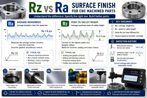
Surface Finish Can Change Function
PEEK surface finish is not only cosmetic.
It may affect sealing, sliding, cleanability, friction, wear, particle retention, or assembly fit.
A rough surface may trap debris.
A smeared surface may hide heat damage.
An over-polished surface may change geometry.
A scratched surface may fail cosmetic or cleanability requirements.
The buyer should identify which surfaces are:
- Sealing surfaces
- Sliding surfaces
- Datum surfaces
- Cosmetic surfaces
- Insulating surfaces
- Fluid-contact surfaces
- Bore surfaces
- Mating surfaces
Without this information, the supplier may improve the wrong area and miss the functional one.
For surface finish selection and inspection planning, review our CNC surface finishes guide.
When PEEK May Be the Wrong Material
A good machining supplier should not pretend PEEK is always the answer.
PEEK is a strong engineering plastic, but it still has limits.
PEEK may not be the best choice when the part requires:
- Very high stiffness with minimal deflection
- Extremely tight flatness on large thin plates
- Metal-like thermal stability
- High structural load with thin geometry
- Sharp edges that must stay perfectly rigid
- Very tight press-fit behavior without creep concern
- Heavy clamping load in assembly
- Low-cost production where material price dominates
- A geometry that releases too much stress after machining
In these cases, the material should be reviewed before production.
Possible alternatives may include aluminum, stainless steel, other engineering plastics, filled PEEK grades, or a design change that adds support, thickness, ribs, inserts, or relaxed tolerance zones.
The best result may not come from forcing PEEK to behave like metal.
It may come from designing the part around what PEEK does well.
How Rapid Efficient Reviews PEEK Tolerance Drift
For PEEK parts, our review does not stop at the material name.
We look for the features most likely to move.
That includes thin walls, large pockets, long slots, sealing faces, bores, threads, unsupported plates, cosmetic faces, and areas with heavy material removal.
Before quotation, we may review:
- Whether the material grade is suitable
- Which dimensions control assembly
- Whether the part should be inspected free-state or restrained
- Whether roughing and finishing should be separated
- Whether stabilization time is needed before final inspection
- Whether the fixture may distort the part
- Whether burr removal may change functional edges
- Whether packaging needs to support thin geometry
This review helps turn a PEEK part from a risky plastic machining job into a controlled manufacturing process.
Send Your PEEK Drawing for Tolerance Drift Review
Send your 2D drawing, 3D CAD file, PEEK grade, quantity, critical dimensions, wall thickness, thread requirements, surface finish, stabilization needs, inspection condition, packaging requirements, and delivery target.
Our team will review machining sequence, clamping method, heat-control risk, burr-control route, tolerance stability, inspection condition, and packaging needs before quotation.
CTA Button: Upload Your Drawing