Stable CNC machining depends on more than entering a program and pressing cycle start.
The machine, cutting tool, fixture, workpiece, CNC program, offsets, coolant, inspection method, and operator actions must work as one controlled system. A weakness in any one of these areas can cause dimensional errors, tool failure, machine damage, or personal injury.
Good machining principles focus on process stability and repeatability. Good safety practices prevent people from being exposed to rotating parts, moving axes, flying chips, sharp tools, coolant, unexpected machine movement, and stored energy.
This article provides general manufacturing and safety guidance. It is not a replacement for the machine manufacturer’s manual, formal operator training, workplace procedures, risk assessment, or applicable safety regulations.
Quick Answer
The main principles of stable CNC machining are:
- Start with a controlled drawing, model, program, and revision.
- Select suitable material, tools, cutting conditions, and workholding.
- Establish repeatable datums and offsets.
- Verify tool, holder, fixture, stock, and machine clearance.
- Separate roughing, semi-finishing, and finishing when necessary.
- Control chips, heat, tool wear, and part distortion.
- Inspect the first piece and critical features during production.
- Record program, offset, tooling, and process changes.
Essential CNC machining safety precautions include:
- Only trained and authorized personnel should operate the machine.
- Use the required eye, face, hearing, footwear, and other protective equipment.
- Keep machine guards, doors, and interlocks functional.
- Do not reach into the machining area while motion is possible.
- Keep loose clothing, jewelry, hair, and unsuitable gloves away from rotating parts.
- Confirm the tool, holder, fixture, workpiece, program, and offsets before cutting.
- Stop the machine before removing chips, measuring the part, or checking a suspected problem.
- Use an approved hazardous-energy isolation procedure before servicing or maintenance.
- Follow the machine manual and the workplace’s approved operating procedure.
CNC Machining Is a Controlled System
A CNC machine follows programmed commands, but the program alone does not guarantee a correct part.
The final result also depends on:
- Drawing and model accuracy
- Material grade and condition
- Stock size and orientation
- Machine condition
- Workholding rigidity
- Datum selection
- Tool geometry
- Tool length and runout
- Cutting parameters
- Toolpath strategy
- Coolant and chip evacuation
- Temperature
- Part stiffness
- Inspection method
- Operator verification
The process should therefore be treated as a connected system rather than a series of independent machine movements.
Principle 1: Begin with Controlled Requirements
Machining should begin with the correct project information.
Before programming or setup, confirm:
- 3D model
- Controlled 2D drawing
- Drawing revision
- Material grade
- Temper, hardness, or heat-treatment condition
- Quantity
- Functional datums
- Critical dimensions
- Geometric tolerances
- Threads
- Surface roughness
- Surface treatment
- Inspection requirements
- Packaging requirements
The 3D model normally defines geometry, while the controlled drawing defines dimensions, datums, tolerances, finishes, threads, notes, and acceptance requirements.
Conflicts between the model, drawing, purchase order, and RFQ should be resolved before production.
A machine can follow an incorrect program very accurately. Process control must therefore begin before the tool touches the material.
Principle 2: Select a Stable Manufacturing Route
The process planner should decide which manufacturing method and setup sequence provide the best combination of access, rigidity, repeatability, and inspection capability.
Possible operations include:
- CNC milling
- CNC turning
- Turn-mill machining
- Indexed multi-axis machining
- Simultaneous five-axis machining
- Drilling
- Boring
- Reaming
- Thread milling
- Tapping
- Grinding
- EDM for suitable features
The most advanced machine is not automatically the best option.
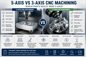
A three-axis process with stable fixtures may be more reliable than a complicated five-axis strategy for a suitable prismatic part. Five-axis machining becomes valuable when it improves tool access, shortens tool overhang, reduces manual repositioning, or controls complex surfaces.
The route should be selected according to actual geometry, quantity, tolerance, material, tooling, inspection, and cost.
For a complete production sequence from drawing review to final inspection, see our guide to the CNC machining process.
Principle 3: Establish Reliable Datums
Datums connect the drawing, fixture, CNC coordinate system, and inspection program.
A good datum strategy should provide:
- Stable physical contact
- Repeatable part location
- Clear orientation
- Access for machining
- Access for inspection
- Functional relationships to the finished part
The primary datum establishes the main orientation. The secondary datum controls another direction, and the tertiary datum completes the location.
Machining datums and design datums are not always the same.
Temporary machining features may be required when:
- The final datum does not exist yet.
- The design datum is too small or flexible for stable location.
- The feature becomes accessible only after roughing.
- The original stock surface will be removed.
- A later operation requires a new locating system.
The process plan should explain how the coordinate system will transfer from temporary references to the final drawing datums.
Principle 4: Use Secure and Repeatable Workholding
The workpiece must resist cutting forces without moving, lifting, slipping, or deforming.
Common workholding methods include:
- Vises
- Chucks
- Collets
- Soft jaws
- Fixture plates
- Custom fixtures
- Locating pins
- Support blocks
- Sacrificial tabs
- Vacuum fixtures for suitable parts
- Magnetic workholding for suitable materials and operations
A fixture performs three different functions:
- Locating the part
- Supporting the part
- Clamping the part
These functions should not be confused.
Excessive clamping force can distort thin walls, flexible plates, rings, housings, or long components. Insufficient force can allow the workpiece to move during cutting.
The fixture should provide enough support near the cutting area without blocking the tool, holder, probe, coolant, or chip flow.
Before machining, verify:
- Fixture fasteners
- Jaw or chuck condition
- Locator cleanliness
- Contact surfaces
- Clamp direction
- Workpiece seating
- Required torque or loading procedure
- Tool and holder clearance
- Spindle and fixture clearance
- Axis travel
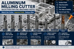
Principle 5: Match the Tool to the Material and Feature
Tool selection should consider:
- Workpiece material
- Material hardness
- Feature size
- Pocket depth
- Hole depth
- Internal radius
- Tool reach
- Holder clearance
- Surface-finish requirement
- Machine rigidity
- Coolant delivery
- Production quantity
Long tool overhang reduces rigidity and can increase:
- Chatter
- Tool deflection
- Wall taper
- Dimensional variation
- Poor surface finish
- Tool breakage
- Corner damage
Where possible, reduce overhang by changing the setup, using a larger internal radius, selecting a stronger tool, or adjusting the tool orientation.
Tool and holder runout should also be controlled. Excessive runout can cause uneven cutting-edge load, premature wear, poor hole quality, and inconsistent surface finish.
Principle 6: Use Appropriate Cutting Conditions
Spindle speed, feed rate, axial depth, radial engagement, coolant, and toolpath should match the material, tool, machine, fixture, and feature.
More speed is not always more efficient.
An aggressive cutting condition may increase:
- Tool load
- Heat
- Vibration
- Deflection
- Burr formation
- Work hardening
- Part movement
- Tool failure
A cutting condition that works on a rigid block may not work on a thin wall or a long unsupported shaft.
Process adjustments should be based on controlled observation and measurement, including:
- Spindle load
- Chip shape
- Chip color where relevant
- Cutting sound
- Vibration
- Tool wear
- Surface finish
- Feature size
- Part temperature
- Fixture condition
Parameter changes should be documented rather than made repeatedly without traceability.
Principle 7: Separate Roughing and Finishing
Roughing
Roughing removes most of the material while preserving:
- Fixture stability
- Datum surfaces
- Temporary supports
- Finishing allowance
- Critical feature protection
The roughing strategy should balance material-removal rate with tool life, cutting force, heat, chip evacuation, and part stability.
Semi-Finishing
Semi-finishing can create more uniform stock before the final pass.
It may also reveal:
- Part movement
- Distortion
- Remaining-stock variation
- Tool-access problems
- Weak walls
- Fixture interference
Finishing
Finishing should focus on the functional features that control fit and assembly, including:
- Datum surfaces
- Bearing seats
- Sealing surfaces
- Critical bores
- Hole patterns
- Mating faces
- Threads
- Profiles
- Surface-finish areas
Heavy material removal should normally be completed before final dimensional control whenever the geometry allows.
Principle 8: Control Chips, Coolant, and Heat
Chips affect both machining quality and operator safety.
Poor chip evacuation can cause:
- Chip recutting
- Surface scratches
- Tool damage
- Heat buildup
- Blocked coolant flow
- Burrs
- Broken drills
- Packed deep pockets
The process may require:
- Suitable toolpath direction
- Through-tool coolant
- Air or coolant delivery
- Peck drilling
- Staged depth cutting
- Part reorientation
- Chip-clearance pauses
- Open evacuation paths
Coolant selection and concentration should follow the material, operation, machine requirements, and workplace procedure.
Poorly managed coolant can contribute to:
- Reduced tool life
- Corrosion
- Residue
- Odor
- Mist exposure
- Skin irritation
- Bacterial growth
- Staining of finished parts
Coolant leaks, excessive mist, abnormal odor, or visible contamination should be reported and corrected according to the workplace procedure.
Principle 9: Verify the Program Before Full Cutting
CAM simulation is valuable, but it does not replace verification on the actual machine.
Before the first cut, confirm:
- Correct program name
- Correct revision
- Correct work offset
- Correct tool numbers
- Correct tool-length offsets
- Correct tool-diameter or wear offsets
- Correct stock orientation
- Correct fixture
- Correct spindle direction
- Correct coolant command
- Safe tool-change positions
- Safe approach and retract movements
- Fixture clearance
- Holder clearance
- Remaining machine travel
Depending on the machine and approved procedure, verification may include:
- Simulation
- Graphics check
- Controlled dry run
- Air cut
- Reduced rapid movement
- Single-block execution
- Feed hold readiness
- First-pass observation from a safe position
The operator should not assume that a previously used program is still correct. A changed tool, fixture, offset, stock size, program revision, or machine can change the risk.
Principle 10: Use First-Piece and In-Process Inspection
The first part should be checked before full production continues.
First-piece inspection may include:
- Overall dimensions
- Datum surfaces
- Bore diameters
- Hole positions
- Threads
- Wall thickness
- Flatness
- Parallelism
- Perpendicularity
- Runout
- Surface roughness
- Visual defects
The inspection scope should follow the drawing and control plan.
In-process checks may be needed when:
- Tools wear quickly.
- The material work-hardens.
- The part is flexible.
- The batch is large.
- Critical dimensions change with temperature.
- Several setups transfer the datum system.
- Surface treatment affects dimensions.
- Tool breakage could damage later features.
For tolerance and datum planning, review our CNC machining tolerances guide.
For inspection planning and documentation, see our quality assurance process.
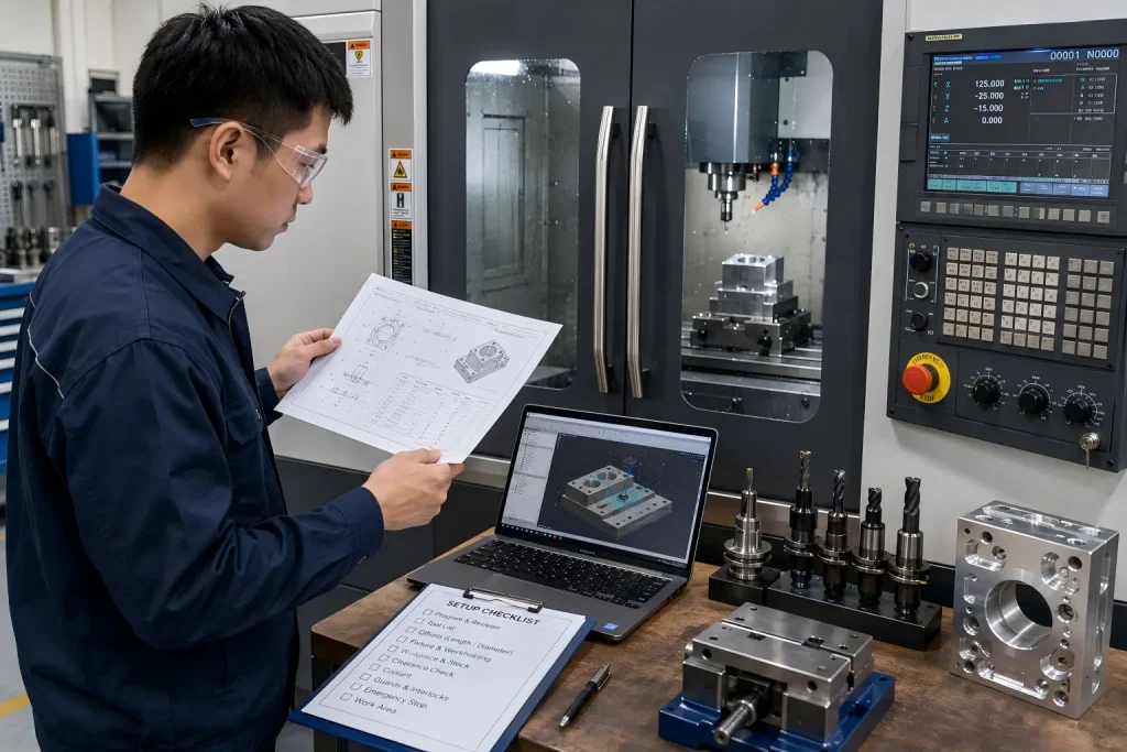
Safety Before Starting the Machine
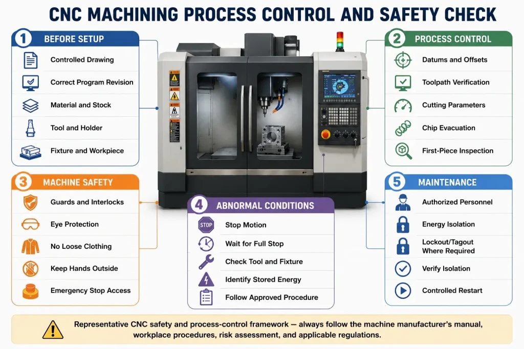
Only trained and authorized personnel should operate or set up CNC equipment.
Personal Protective Equipment
Use protective equipment required by the workplace risk assessment and applicable rules.
This may include:
- Safety glasses with suitable side protection
- Face protection where required
- Safety footwear
- Hearing protection
- Protective clothing appropriate to the operation
- Chemical-resistant protection when handling coolant or cleaners
Personal protective equipment does not replace machine guarding or safe operating procedures.
Clothing, Hair, Jewelry, and Gloves
Keep the following away from rotating or moving equipment:
- Loose sleeves
- Loose clothing
- Necklaces
- Bracelets
- Rings
- Long hair
- Rags
- Cords
- Unsecured gloves
Gloves may protect against sharp material or chemicals during approved handling tasks, but they can create an entanglement risk near rotating spindles, chucks, tools, or workpieces.
Follow the workplace procedure for when gloves must be removed.
Machine Guards and Interlocks
Before operation, confirm that:
- Doors and guards are installed.
- Interlocks operate as intended.
- Viewing windows are in acceptable condition.
- Emergency stops are accessible.
- Warning labels are visible.
- No safety device has been bypassed or defeated.
Do not operate a machine with a damaged or intentionally disabled guard or interlock.
A closed door does not correct an unsafe fixture, incorrect offset, loose tool, or wrong program. Guarding and process verification are both required.
Tool, Holder, and Spindle Check
Confirm:
- The correct tool is installed.
- The tool is not visibly damaged.
- The cutting edge is suitable.
- The tool is correctly seated.
- The holder is clean.
- The retention system is correct where applicable.
- Tool length matches the program.
- The holder clears the workpiece and fixture.
- The tool-change position is safe.
A tool that is loose, cracked, excessively worn, or incorrectly identified should not be used.
Fixture and Workpiece Check
Confirm:
- The fixture is secured.
- The vise, jaws, chuck, collet, or clamps are in good condition.
- The workpiece is fully seated.
- Locating surfaces are clean.
- Clamp positions match the setup plan.
- The workpiece cannot be pulled out by the cutting force.
- Excess stock does not create a collision.
- Doors can close without interference.
Work Area Check
The area should be free from:
- Loose tools
- Unsecured measuring instruments
- Rags inside the machine
- Unnecessary setup blocks
- Coolant spills
- Trip hazards
- Uncontrolled sharp chips
- Objects placed on the machine enclosure
Anything left inside the machine can become a projectile or collision hazard.
Safety During CNC Machining
Keep the Guarded Area Closed
During automatic machining:
- Keep doors and guards closed.
- Do not bypass interlocks.
- Do not reach into the machining area.
- Do not place tools or hands near moving axes.
- Do not try to catch or redirect chips by hand.
- Do not measure the part while the spindle or workpiece is rotating.
- Do not touch a tool immediately after cutting without considering heat and sharp edges.
Wait until all programmed and residual movement has stopped before accessing the machining area.
Monitor from a Safe Position
The operator should watch for:
- Unusual noise
- Unexpected vibration
- Increased spindle load
- Coolant failure
- Chip packing
- Smoke
- Burning smell
- Tool breakage
- Workpiece movement
- Fixture loosening
- Abnormal axis movement
- Collision risk
Monitoring does not mean opening the guard and moving closer to a rotating tool.
Use the control display, viewing window, camera, load monitor, feed hold, and other approved machine functions.
Responding to an Abnormal Condition
When an abnormal condition occurs:
- Use feed hold, cycle stop, or emergency stop as required by the situation and approved procedure.
- Wait until all motion has stopped.
- Do not immediately reach into the machine.
- Identify whether stored, pneumatic, hydraulic, gravitational, electrical, spindle, or mechanical energy remains.
- Follow the approved isolation procedure when the work goes beyond normal guarded operation.
- Inspect the tool, holder, fixture, workpiece, offsets, program, and machine before restarting.
- Document the cause and corrective action where required.
An emergency stop stops machine motion, but it should not automatically be treated as a complete hazardous-energy isolation method for maintenance or servicing.
Chip Removal
Chips can be:
- Sharp
- Hot
- Long and entangling
- Contaminated with coolant
- Embedded under the workpiece
- Packed inside a pocket or bore
Do not remove chips with bare hands.
Use approved tools such as:
- Chip hooks
- Brushes
- Scrapers
- Pliers
- Vacuum equipment
- Other shop-approved devices
Stop the machine and follow the required access procedure before clearing chips from the machining area.
Compressed air should only be used when allowed by the machine manufacturer and workplace procedure, with suitable pressure control, guarding, and protection. Never direct chips, coolant, or compressed air toward another person.
Maintenance and Hazardous-Energy Control
Normal operation and maintenance are not the same activity.
Tasks such as the following may expose someone to unexpected movement or stored energy:
- Entering the machine enclosure
- Clearing a serious jam
- Repairing a fixture
- Servicing the spindle
- Working on tool changers
- Accessing conveyors
- Repairing electrical systems
- Working on pneumatic or hydraulic equipment
- Removing guards
- Performing maintenance below unsupported components
Before servicing or maintenance, follow the workplace’s approved hazardous-energy control procedure.
The procedure may require:
- Machine shutdown
- Identification of all energy sources
- Energy isolation
- Lockout or tagout
- Release or restraint of stored energy
- Verification of isolation
- Authorized-person control
- Controlled restoration of energy
A control-panel stop button or emergency stop may not isolate every source of electrical, hydraulic, pneumatic, gravitational, thermal, or mechanical energy.
Only authorized personnel should perform energy isolation and maintenance.
Safety After Machining
After the cycle is complete:
- Confirm the spindle and axes have stopped.
- Remove the workpiece using an approved handling method.
- Consider hot surfaces and sharp edges.
- Do not leave loose chips on fixture locating surfaces.
- Clean the part at the designated station.
- Deburr using the correct tool and protective equipment.
- Inspect the tool for wear or damage.
- Inspect the fixture and jaws.
- Record required offset or program changes.
- Store tools and gauges correctly.
- Clean coolant or oil spills.
- Follow the approved machine shutdown procedure when production is complete.
Do not use the machine spindle, table, or enclosure as general storage.
Common Unsafe CNC Machining Practices
The following practices should not be accepted:
- Bypassing a door interlock
- Running an unverified program at full rapid speed
- Reaching inside before all movement stops
- Holding a part by hand during CNC cutting
- Measuring a rotating part
- Wearing loose gloves near a rotating spindle or chuck
- Removing chips with bare hands
- Using a damaged tool or holder
- Ignoring unusual vibration or spindle load
- Leaving tools inside the enclosure
- Changing offsets without recording the reason
- Restarting after a collision without inspecting the machine and setup
- Treating the emergency stop as a complete maintenance isolation method
- Allowing untrained personnel to operate or repair the machine
How Processing Principles Affect Finished-Part Quality
Stable machining principles directly affect:
- Dimensional consistency
- Datum relationships
- Hole position
- Bore size
- Flatness
- Runout
- Thread quality
- Surface roughness
- Burr control
- Tool marks
- Part deformation
- Repeatability between batches
A supplier should therefore evaluate more than the nominal machine specification.
Buyers should also review:
- Drawing control
- DFM capability
- Fixture strategy
- Program verification
- First-piece approval
- Tool-wear control
- In-process inspection
- Final inspection
- Nonconformance handling
- Documentation
- Packaging
For tool-life risks and common wear patterns, review our guide to CNC tool wear.
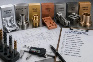
RFQ Checklist
For an effective CNC machining review, provide:
- 3D CAD model
- Controlled 2D drawing
- Drawing revision
- Exact material grade
- Temper or condition
- Quantity
- Critical dimensions
- Datums
- Geometric tolerances
- Threads
- Surface roughness
- Surface treatment
- Cosmetic surfaces
- Inspection requirements
- Required reports
- Packaging requirements
- Mating-part information
- Intended operating environment
These details allow the supplier to plan tooling, workholding, setup sequence, inspection, finishing, and process controls before machining begins.
How Rapid Efficient Supports CNC Machining Projects
Rapid Efficient supports custom CNC machining for metal and engineering-plastic components, including prototypes, low-volume production, and repeat orders.
Project support may include:
- Drawing and manufacturability review
- Material and stock review
- CNC milling and turning
- Multi-axis process planning
- Fixture and datum discussion
- Tool-access review
- First-piece inspection
- In-process dimensional checks
- Surface-finishing coordination
- CMM reports when requested
- Material documentation when requested
- Cleaning, packaging, and international delivery coordination
Final feasibility depends on the material, geometry, quantity, tolerances, surface treatment, inspection scope, and documentation requirements.
Learn more about our CNC milling services.
After receiving complete drawings, models, quantities, and project requirements, Rapid Efficient can review manufacturing risks and typically provide quotation feedback within 24 hours.
FAQ
What are the basic principles of CNC machining?
The main principles are controlled requirements, stable workholding, reliable datums, suitable tools and cutting conditions, verified programs and offsets, controlled roughing and finishing, chip and heat management, and planned inspection.
What should be checked before starting a CNC machine?
Check the program and revision, tool list, offsets, fixture, workpiece seating, stock orientation, holder clearance, spindle direction, coolant, machine guards, interlocks, and work area.
Can a CNC program be trusted after simulation?
Simulation reduces risk but does not replace verification on the actual machine. The real fixture, tool lengths, holders, offsets, stock, machine travel, and program revision must still be checked.
Should gloves be worn during CNC machining?
Gloves may be appropriate for some material-handling or chemical-handling tasks, but loose gloves can create an entanglement hazard near rotating spindles, chucks, tools, or workpieces. Follow the workplace procedure and remove gloves where rotation creates a risk.
Can an operator remove chips while the CNC machine is running?
No one should reach into a hazardous machining area while motion is possible. Stop the machine, wait for movement to stop, and use approved chip-removal tools and procedures.
Is pressing the emergency stop enough before maintenance?
Not necessarily. An emergency stop may stop motion without isolating all electrical, hydraulic, pneumatic, gravitational, thermal, or stored mechanical energy. Maintenance may require an approved hazardous-energy isolation procedure.
Why is first-piece inspection important?
It confirms that the program, offsets, tooling, fixture, datums, and machining sequence produce the required features before the full batch continues.
What causes an accurate CNC program to produce bad parts?
Possible causes include incorrect offsets, tool wear, tool runout, part movement, fixture distortion, thermal change, wrong material, poor chip evacuation, machine condition, incorrect inspection alignment, or drawing ambiguity.
Request a CNC Machining Review
Send Rapid Efficient your 2D drawing, 3D model, material, quantity, tolerances, surface treatment, and inspection requirements.
We can review:
- Manufacturing route
- Workholding
- Datum transfer
- Tool access
- Setup count
- Thin-wall and distortion risks
- Critical tolerances
- Inspection requirements
- Surface-finishing allowances
- Documentation scope
Clear process planning before production helps reduce setup mistakes, avoidable tool problems, inspection disputes, and unnecessary rework.