Quick Answer
A typical CNC machining process includes seven main stages:
- Drawing and RFQ review
- DFM and process planning
- Material, tooling, and fixture preparation
- CAM programming and toolpath simulation
- Machine setup and first-piece verification
- Roughing, finishing, and in-process control
- Final inspection, surface finishing, and packaging
The exact order can change with the part geometry, material, quantity, tolerances, surface finish, and inspection requirements.
For buyers, the process begins before the machine starts. Drawing conflicts, material condition, datum selection, tool access, setup count, and inspection requirements should be reviewed before production.
CNC Machining Process Overview
| Step | Main Work | Key Output |
|---|---|---|
| 1. Drawing review | Check geometry, material, tolerances, threads, finish, and quantity | Clear manufacturing requirements |
| 2. DFM and process planning | Review tool access, setups, datums, stock form, and inspection risks | Manufacturing and inspection plan |
| 3. Production preparation | Prepare material, fixtures, cutting tools, gauges, and setup documents | Ready-to-machine production package |
| 4. CAM programming | Create toolpaths, simulate machining, and generate machine-specific code | Verified CNC program |
| 5. Machine setup | Install the fixture, set work and tool offsets, and verify the first setup | Stable and repeatable setup |
| 6. Machining | Complete roughing, semi-finishing, finishing, and in-process checks | Machined component |
| 7. Final verification | Deburr, clean, finish, inspect, document, and package the part | Approved and protected finished part |
This is a practical manufacturing workflow rather than a machine-specific operating procedure. Individual suppliers may combine or separate certain stages depending on the part and production quantity.
1. Drawing and RFQ Review
The CNC machining process should begin with a review of the 3D model, 2D drawing, and quotation requirements.
The supplier should confirm:
- Material grade and condition
- Prototype or production quantity
- Functional datums
- Critical tolerances
- Hole and thread requirements
- Surface roughness
- Anodizing, plating, passivation, or other finishes
- Cosmetic surfaces
- Inspection reports
- Packaging and delivery requirements
The 3D model defines the part geometry, while the 2D drawing normally defines tolerances, datums, threads, finish notes, and inspection requirements.
Any conflict between the model, drawing, and RFQ should be resolved before programming begins. Starting production with unclear requirements can lead to incorrect material purchasing, unnecessary tight tolerances, additional setups, or inspection disputes.
For design features that may affect machining cost and process stability, review our CNC machining design guide.
2. DFM Review and Process Planning
Before machining, the supplier should determine whether the part can be produced consistently, inspected reliably, and delivered at a practical cost.
The process review should consider:
- Milling, turning, turn-mill, or five-axis machining
- Number of setups
- Tool access
- Fixture and clamping surfaces
- Datum transfer between setups
- Thin walls and flexible features
- Deep pockets and long tool reach
- Internal corner radii
- Hole depth and chip evacuation
- Thread engagement
- Surface-finishing allowances
- Inspection access
The process plan should also identify which features are completed during roughing, semi-finishing, and final finishing.
Setup and Datum Planning
The supplier should choose stable reference surfaces that can support both machining and inspection.
Additional setups may be necessary when features cannot be reached from one direction. However, every repositioning operation can add:
- Fixture preparation
- Realignment time
- Datum-transfer error
- Additional handling
- First-piece verification
- Intermediate inspection
The goal is not always to machine the entire part in one setup. The goal is to use the fewest setups that still provide stable clamping, safe tool access, predictable dimensions, and reliable inspection.
Tolerance Review
Tight tolerances should be applied to functional features rather than every dimension.
Before quotation, the supplier should identify:
- Fits and mating surfaces
- Bearing or sealing features
- Hole position requirements
- Flatness and parallelism
- Runout
- Datum relationships
- Dimensions affected by surface finishing
This review helps prevent unnecessary machining and inspection cost.
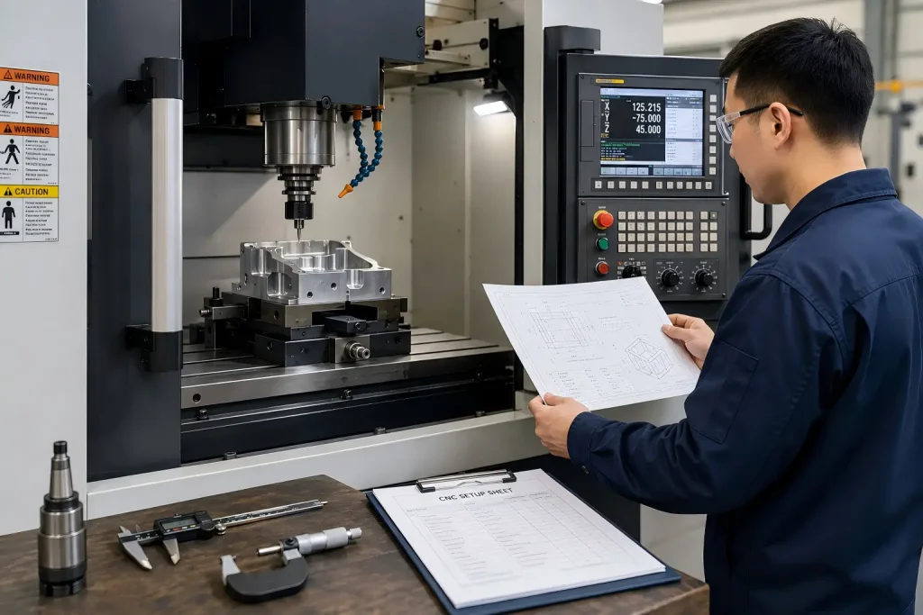
Correct workholding is important for both safety and machining results, while setup planning and datum selection determine how reliably features can be produced across multiple operations.
3. Material, Tooling, and Fixture Preparation
Once the manufacturing plan is confirmed, the supplier can prepare the material, cutting tools, workholding, and inspection equipment.
Material Preparation
The material specification should include more than a general family such as aluminum or stainless steel.
Important information may include:
- Exact alloy or grade
- Temper or heat-treatment condition
- Hardness
- Plate, bar, extrusion, casting, or forging
- Material thickness and stock size
- Grain or rolling direction when relevant
- Material certificate requirements
Incoming stock should be checked for the correct grade, size, visible damage, and condition before machining.
The selected stock should provide enough machining allowance without creating unnecessary material waste or excessive roughing time.
Cutting-Tool Preparation
Cutting tools should be selected according to:
- Material
- Feature geometry
- Hole and thread sizes
- Tool reach
- Surface-finish requirement
- Machine capability
- Expected quantity
- Tool-life requirement
Special tools may be required for deep bores, undercuts, internal grooves, small threads, or difficult-to-reach surfaces.
Fixture Preparation
The fixture must locate the workpiece consistently and resist machining forces without damaging or distorting the part.
Fixture preparation may include:
- Standard vises and chucks
- Soft jaws
- Custom fixtures
- Support blocks
- Vacuum or magnetic workholding
- Sacrificial tabs
- Additional support for thin walls
The chosen fixture should also provide sufficient access for cutting tools, probes, and inspection equipment.
4. CAM Programming and Toolpath Simulation
The programmer converts the approved design and process plan into machining operations.
A CAM setup normally defines:
- Machine and coordinate orientation
- Stock size and position
- Workholding
- Cutting tools
- Tool lengths and holders
- Roughing operations
- Semi-finishing operations
- Finishing operations
- Drilling, boring, reaming, and threading
- Safe approach and retract movements
Toolpath Planning
A practical toolpath should reduce unnecessary air cutting, repeated entries, abrupt load changes, and excessive tool changes.
The program should also account for:
- Tool reach
- Collision clearance
- Chip evacuation
- Remaining stock
- Thin-wall support
- Finishing allowance
- Tool deflection
- Surface-finish direction
Simulation and Verification
The toolpaths should be simulated before production to check:
- Tool and holder collisions
- Fixture interference
- Incorrect stock orientation
- Excessive tool travel
- Unmachined areas
- Unexpected overcutting
- Unsafe entry or retract movements
After simulation, a suitable post processor converts the CAM operations into machine-specific CNC code.
The programmer may also prepare a setup sheet containing tool numbers, offsets, fixture information, stock orientation, and operation notes.
Autodesk’s documented manufacturing workflow follows the same general sequence: create the setup, program the toolpaths, simulate them, generate machine-specific G-code, and then make the part.
5. Machine Setup and First-Piece Verification
Before cutting begins, the operator should confirm that the actual machine setup matches the approved process plan.
The setup normally includes:
- Cleaning the fixture and locating surfaces
- Installing and checking the workholding
- Loading the correct tools
- Confirming tool numbers and holders
- Setting tool-length and diameter offsets
- Setting the work coordinate system
- Confirming stock orientation
- Loading the correct CNC program
- Checking coolant and chip evacuation
- Reviewing the setup sheet
Work offsets may be established using probes, edge finders, indicators, or other suitable measurement methods. Tool offsets may be measured manually or with a tool-setting system.
The correct method depends on the machine, controller, fixture, part, and available measurement equipment.
Program and Setup Verification
Before full cutting, the operator should verify:
- Program name and revision
- Tool list
- Work offset
- Tool offsets
- Fixture clearance
- Safe approach positions
- Spindle direction
- Coolant delivery
- Stock dimensions
Simulation does not replace verification on the actual machine.
Depending on the machine and process, verification may include a controlled dry run, air cut, reduced rapid movement, single-block execution, or other approved shop procedure.
First-Piece Inspection
The first part should be checked before the full batch continues.
First-piece verification may include:
- Overall dimensions
- Datum location
- Hole position
- Bore diameter
- Threads
- Flatness
- Runout
- Critical wall thickness
- Surface finish
Any offset, tool-wear, fixture, or program adjustment should be made before repeat production.
Workpiece probes can automate setup and part verification, while tool-setting systems establish tool reference values and check wear or breakage.
6. Roughing, Finishing, and In-Process Control
Machining is usually divided into stages rather than completing every feature in one aggressive operation.
Roughing
Roughing removes most of the unwanted material while leaving controlled stock for later operations.
The roughing strategy should balance:
- Material-removal rate
- Tool life
- Cutting force
- Machine power
- Fixture stability
- Chip evacuation
- Heat generation
- Part deformation
For thin walls, large pockets, long shafts, or stress-sensitive materials, balanced material removal may be more important than maximum cutting speed.
Semi-Finishing
Semi-finishing creates a more even machining allowance before the final pass.
It may help:
- Reduce variable cutting loads
- Correct distortion after roughing
- Prepare consistent stock for finishing
- Protect critical surfaces
- Improve final dimensional control
Some parts may require unclamping, stress relief, turning over, or an intermediate inspection before final finishing.
Finishing
Finishing produces the final dimensions, geometry, and machined surface.
The finishing strategy may use:
- Dedicated finishing tools
- Reduced and stable cutting loads
- Tool-wear compensation
- Controlled coolant delivery
- Shorter tool overhang
- Additional dimensional checks
- Separate passes for sealing, bearing, or cosmetic surfaces
Cutting Parameters
Cutting speed, spindle speed, feed, and depth of cut should be selected for the specific operation.
The correct values depend on:
- Milling, turning, drilling, boring, reaming, or threading
- Workpiece material and hardness
- Tool diameter or workpiece diameter
- Tool material and coating
- Machine rigidity
- Fixture stability
- Tool overhang
- Required finish
- Coolant conditions
There is no single spindle speed, feed, drilling allowance, or reaming speed suitable for every CNC machining project.
In-Process Monitoring
During machining, the supplier may monitor:
- Tool wear
- Chip shape and evacuation
- Cutting noise and vibration
- Coolant flow
- Dimensional movement
- Surface condition
- Fixture stability
- Broken or damaged tools
Critical dimensions may be checked between operations so that tool wear or process drift can be corrected before the part is completed.
Sandvik publishes separate formula definitions for milling and turning because cutting speed, feed per tooth, feed per revolution, cutter diameter, and workpiece diameter are not interchangeable across operations.
7. Final Inspection, Surface Finishing, and Packaging
Machining is not complete when the cutting tool stops.
The finished part may still require deburring, cleaning, surface finishing, final inspection, documentation, and protective packaging.
Deburring and Cleaning
Machined parts should be checked for:
- Sharp edges
- Hole burrs
- Thread burrs
- Chips in blind holes
- Coolant residue
- Oil and contamination
- Loose abrasive particles
- Damage from handling
Deburring must not change critical edges, sealing surfaces, hole positions, or controlled dimensions.
Dimensional Inspection
Inspection should follow the drawing and agreed inspection plan.
Depending on the part, inspection may include:
- Calipers and micrometers
- Height gauges
- Bore gauges
- Pin and thread gauges
- Indicators
- Surface-roughness measurement
- Optical inspection
- CMM measurement
Critical requirements may include:
- Diameter
- Hole position
- Flatness
- Parallelism
- Perpendicularity
- Runout
- Thread size
- Profile
- Datum relationships
For guidance on realistic requirements and inspection planning, review our CNC machining tolerances resource.
Surface Finishing
If the drawing requires anodizing, passivation, plating, painting, polishing, bead blasting, or another finish, the part may need inspection both before and after finishing.
The supplier should confirm:
- Finish type
- Coating thickness
- Cosmetic requirements
- Masked areas
- Threads and bores
- Electrical contact surfaces
- Dimensional allowance
- Color and gloss expectations
Final Verification and Reports
After all required operations, the supplier should confirm that the part meets the agreed drawing and finish requirements.
Reports may include:
- Dimensional inspection report
- CMM report
- Material certificate
- Surface-finish record
- Coating certificate
- First-article report
- Thread or gauge results
For parts requiring coordinate measurement, see our guide to CMM inspection for CNC machined parts.
Packaging
Packaging should protect:
- Cosmetic surfaces
- Threads
- Sharp or delicate features
- Sealing surfaces
- Precision bores
- Coatings
- Parts vulnerable to corrosion
Parts may require individual wrapping, separators, protective plugs, corrosion protection, or custom trays depending on their geometry and delivery conditions.
Machine-tool probing can support setup, in-process control, and part verification, but final inspection requirements should still be defined by the drawing and agreed inspection plan.
Information to Provide Before CNC Machining
| RFQ Item | What to Provide | Why It Matters |
|---|---|---|
| 3D model | STEP, STP, or another usable solid model | Supports geometry review and CAM programming |
| 2D drawing | Tolerances, datums, threads, finishes, and notes | Defines requirements not fully shown in the model |
| Material | Exact grade, condition, hardness, and certificate needs | Affects sourcing, tools, cutting parameters, and inspection |
| Quantity | Prototype quantity and expected repeat volume | Affects setup, fixtures, tooling, and unit cost |
| Critical dimensions | Fits, hole positions, flatness, runout, and datum relationships | Helps plan finishing and inspection |
| Surface finish | Roughness, anodizing, plating, polishing, or coating | Affects machining allowance, masking, and lead time |
| Inspection | Standard inspection, CMM report, full report, or first-article requirements | Defines inspection work before quotation |
| Delivery requirement | Target date, packaging, and shipping conditions | Helps plan production and protection |
Complete RFQ information allows the supplier to review process risk before material purchasing and programming begin.
FAQ: CNC Machining Process
How Many Steps Are in the CNC Machining Process?
A practical CNC machining process can be summarized in seven main stages: drawing review, DFM planning, production preparation, CAM programming, machine setup, machining, and final verification.
Some projects may combine or divide these stages depending on geometry, quantity, finishing, and inspection requirements.
Does Every CNC Part Follow the Same Process?
No. A simple turned spacer, a five-axis housing, a thin aluminum plate, and a hardened-steel component may require different machines, setups, tooling, inspection, and finishing sequences.
When Should Tolerances Be Reviewed?
Tolerances should be reviewed before quotation and programming. Tight requirements can affect material selection, fixture design, machining sequence, inspection method, cost, and lead time.
Why Is First-Piece Inspection Important?
First-piece inspection confirms that the program, offsets, tools, fixture, and process can produce the required dimensions before the full batch continues.
Is Surface Finishing Done Before or After Inspection?
Both may be required. Critical dimensions are often checked before finishing, while final dimensions, appearance, masking, and coating results may need verification after finishing.
What Files Are Needed for a CNC Machining Quote?
A STEP file and a 2D drawing are usually the best starting point. Also provide the material, quantity, surface finish, inspection requirements, and target delivery date.
Does CAM Simulation Guarantee That the Part Will Be Correct?
No. Simulation can identify many toolpath, stock, holder, and collision risks, but the actual machine setup, offsets, tools, fixture, material, and first-piece result must still be verified.
Conclusion
The CNC machining process begins with clear requirements and ends with verified, protected finished parts.
Drawing review, DFM, material preparation, CAM programming, setup, machining, inspection, surface finishing, and packaging must work together. Problems found before programming are usually easier and less expensive to correct than problems discovered after machining begins.
For buyers, the most useful preparation is to provide a complete 3D model, 2D drawing, material specification, quantity, tolerance requirements, surface finish, and inspection needs before quotation.
Review Your CNC Machining Project
Rapid Efficient can review your drawing, material, geometry, tolerances, surface finish, inspection requirements, and order quantity before quotation.
Send the STEP file, 2D drawing, quantity, material specification, finish, and delivery requirement for a project-specific manufacturing review.
Learn more about our CNC machining services for custom prototypes, low-volume parts, and repeat production.