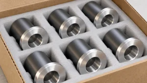
Quick Answer
Contamination and damage in precision CNC machining are commonly caused by chips trapped between locating surfaces, dirty toolholders, unstable coolant condition, tramp oil, incorrect lubricants, excessive clamping force, incompatible cleaning chemicals, poor handling, and inadequate packaging.
Effective control must continue through the complete production route:
- Incoming material inspection
- Fixture and datum cleaning
- Tool and toolholder preparation
- Chip and coolant management
- Controlled machining parameters
- Part cleaning and drying
- Dimensional and cosmetic inspection
- Protected storage and packaging
A clean workshop alone does not guarantee clean or undamaged parts. The supplier must also protect functional datums, threads, bores, sealing surfaces, cosmetic faces, coating areas, and inspection surfaces throughout machining and delivery.
For buyers, the RFQ should identify critical surfaces, prohibited contaminants, cleaning restrictions, finish requirements, inspection conditions, and packaging expectations before production.
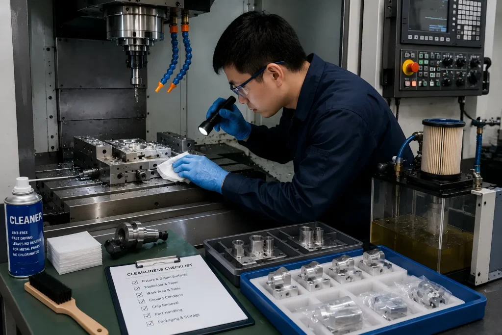
CNC Machining Contamination and Damage Control Overview
| Risk Source | Possible Part or Process Damage | Practical Control | Buyer Should Define |
|---|---|---|---|
| Chips on datum or fixture surfaces | Position error, dents, unstable clamping, and runout | Clean and inspect all locating surfaces before loading the part | Critical datums and geometric requirements |
| Dirty spindle taper or toolholder | Tool runout, vibration, poor finish, and tool failure | Keep tapers, collets, holders, and tool seats clean and undamaged | Surface finish and critical tool-access features |
| Incorrect clamping | Deformation, jaw marks, scratches, and unstable dimensions | Use controlled force, clean soft jaws, and suitable support | Cosmetic faces, thin walls, and clamping restrictions |
| Coolant outside its specified condition | Corrosion, residue, foam, poor tool life, staining, or odor | Maintain concentration and condition according to coolant-supplier instructions | Material, finish, cleanliness, and prohibited fluids |
| Tramp oil and dirty coolant | Smoke, residue, bacteria, poor cleaning, and surface contamination | Remove tramp oil and chips and maintain filtration | Final part-cleanliness requirement |
| Incorrect lubricant or blocked lubrication line | Machine wear, heat, alarms, and unstable movement | Follow the machine OEM specification and inspect delivery, pressure, and leaks | No buyer action unless machine condition affects the parts |
| Incompatible cleaner | Etching, staining, pitting, cracking, or coating failure | Match the cleaner to the material, finish, and contamination | Approved and prohibited cleaning chemicals |
| Poor handling after machining | Fingerprints, scratches, dents, mixed parts, and damaged threads | Use clean trays, separators, plugs, gloves where safe, and controlled storage | Cosmetic acceptance and packaging |
| Incorrect inspection condition | Disputes caused by temperature or material stabilization differences | Define measurement temperature and stabilization when technically necessary | Tight tolerances and acceptance method |
| Inadequate packaging | Contact marks, corrosion, damaged edges, and foreign material | Use separators, wrapping, plugs, corrosion protection, and clean packaging | Transport conditions and unpacking cleanliness |
1. Work Environment and Cleanliness Control
Separate Clean and Dirty Operations
The required cleanliness level depends on the part, material, surface finish, and final application.
A normal CNC workshop does not automatically need cleanroom conditions. However, operations that generate dust or abrasive particles should be separated from final inspection, cleaning, and packaging when contamination could affect the finished part.
Potentially dirty operations include:
- Grinding
- Abrasive blasting
- Heavy deburring
- Polishing
- Rust removal
- Saw cutting
- Chip handling
- Coolant-tank maintenance
Useful controls include:
- Enclosed machining areas
- Scheduled machine and floor cleaning
- Chip collection and filtration
- Covered storage for finished parts
- Separate clean trays for inspected parts
- Dedicated packaging areas
- Clear identification of accepted and nonconforming parts
Do not direct chips, coolant, or compressed air toward electrical cabinets, guideways, open bearings, clean parts, or inspection equipment.
Temperature and Measurement Conditions
Temperature affects the dimensions of the machine, workpiece, fixture, and measuring equipment. The risk becomes more important for:
- Large components
- Aluminum and engineering-plastic parts
- Thin-wall parts
- Tight fits
- Flatness and position requirements
- Parts measured shortly after machining
A fixed workshop requirement of 20°C ±2°C and 40%–60% RH is not necessary for every CNC project.
Instead, the supplier should:
- Avoid direct airflow from heaters or air-conditioning outlets onto the machine
- Avoid placing major heat sources beside precision equipment
- Allow critical parts to stabilize before final measurement
- Record or control temperature when required by the tolerance and inspection plan
- Define the measurement condition for temperature-sensitive parts
ISO 1 establishes 20°C as the standard reference temperature for geometrical and dimensional specifications, but that does not mean every machining workshop must continuously operate at exactly 20°C. The practical control depends on the part, uncertainty and agreed inspection method.
2. Raw Material and Workpiece Protection
Incoming Material Inspection
Before machining begins, check the incoming material against the drawing, purchase specification, and material documents.
The review may include:
- Material grade
- Temper or heat-treatment condition
- Stock form
- Dimensions
- Lot identification
- Visible corrosion
- Scale
- Dents
- Protective film
- Embedded debris
- Oil or unknown surface residue
- Material-certificate requirements
Material with severe corrosion, unknown contamination, deep damage, or inconsistent identification should be isolated until its suitability is confirmed.
Material Cleaning Before Machining
Do not automatically clean every material with an organic solvent or abrasive blasting.
The correct method depends on:
- Aluminum, steel, stainless steel, copper, brass, titanium, or plastic
- Oil, rust, scale, adhesive, dust, or protective-film residue
- Cosmetic or functional surfaces
- Later anodizing, plating, passivation, painting, or bonding
- Part thickness and deformation risk
- Chemical compatibility
Possible methods include:
- Wiping with an approved cleaner
- Water-based degreasing
- Controlled solvent cleaning
- Mechanical rust removal
- Abrasive blasting when the resulting surface is acceptable
- Rinsing and complete drying
Abrasive blasting changes the surface texture and may embed media or damage thin and cosmetic material. It should not be treated as a universal cleaning method.
Workpiece Clamping Protection
Fixture contacts, soft jaws, parallels, chuck jaws, support points, and locating surfaces should be clean before every setup.
A chip trapped beneath the workpiece can cause:
- Datum error
- Part tilt
- Dents
- Unstable clamping
- Runout
- Incorrect hole position
- Scrap during a later setup
Suitable workholding may include:
- Machined soft jaws
- Clean protective films
- Non-marring fixture surfaces
- Vacuum fixtures
- Distributed supports
- Sacrificial tabs
- Custom nests
- Controlled chuck or vise pressure
Loose copper sheets and rubber pads should not be used as a default solution. Copper can mark or interfere with location, while soft rubber can compress, move, or contaminate the workpiece.
For thin-wall or easily distorted parts, the fixture should support the geometry without hiding unstable clamping beneath a soft pad.
3. Tooling, Toolholder, and Chip Control
Tool and Toolholder Cleanliness
Before installing a cutting tool, inspect:
- Cutting edges
- Tool flutes
- Insert seats
- Screws
- Collets
- Toolholder tapers
- Spindle-taper contact surfaces
- Pull studs
- Coolant passages
- Tool runout
Chips, oil films, burrs, or damage between precision contact surfaces can cause runout, poor balance, vibration, unstable tool life, and surface defects.
Damaged tools should not remain in production only because they can still remove material.
The original statement that coated carbide tools should be used to machine “carbide materials” should be deleted. Fully sintered cemented carbide commonly requires grinding, EDM, or other specialized processing rather than ordinary coated-carbide milling tools.
Cutting Parameters and Chip Evacuation
Cutting speed, feed, depth of cut, tool engagement, toolpath, coolant, and chip evacuation should be selected together.
The objective is to prevent:
- Chip recutting
- Built-up edge
- Burr formation
- Excessive heat
- Tool rubbing
- Chatter
- Thin-wall deformation
- Surface scratching
- Chips trapped in blind holes
For thin-wall parts, simply raising spindle speed and lowering feed is not a universal solution.
The correct strategy may involve:
- Balanced stock removal
- Suitable radial and axial engagement
- Sharp tools
- Stable support
- Reduced cutting force
- Consistent tool engagement
- Roughing and finishing separation
- Toolpath direction control
- Effective air or coolant delivery
- Intermediate dimensional checks
Before transferring the part to another setup, remove chips from datum surfaces, threaded holes, counterbores, pockets, and locating features.
4. Coolant and Lubrication Management
Coolant Selection and Maintenance
Coolant should be selected according to the workpiece material, operation, tooling, machine requirements, surface finish, and later cleaning or coating process.
The supplier should monitor:
- Coolant concentration
- Coolant level
- Water quality
- pH or alkalinity when required by the coolant supplier
- Tramp oil
- Chips and sediment
- Filtration
- Foam
- Odor
- Biological contamination
- Rust or staining
- Compatibility with seals and machine components
Coolant concentration should be checked with a suitable refractometer and maintained within the coolant manufacturer’s specified range.
Do not use one universal percentage for every product. A concentration that is too low or too high can affect corrosion protection, tool performance, residue, foam, cleaning, and operator exposure.
Haas specifically recommends checking coolant concentration with a refractometer and verifying it against the coolant manufacturer’s specification.
Coolant residue should be removed when it may interfere with:
- Anodizing
- Plating
- Passivation
- Painting
- Adhesive bonding
- Sealing
- Electrical contact
- Cosmetic inspection
- Clean packaging
Lubrication-System Maintenance
Machine lubrication must follow the machine manufacturer’s instructions.
Routine checks may include:
- Reservoir level
- Correct lubricant
- Pump operation
- Pressure or flow alarms
- Tubing condition
- Fittings
- Metering units
- Delivery to required points
- Active leakage
- Contamination
- Abnormal axis or spindle temperature
Do not use a universal rule that guideway oil or ball-screw lubricant must be replaced every three to six months. Some systems consume lubricant continuously, while others have different inspection and service schedules.
Do not mix lubricants unless compatibility has been confirmed.
For leak causes, pressure problems, damaged tubing, seals, reservoirs, and blocked lubrication components, review our guide to CNC machining center oil leakage.
5. Operator Practices and Safe Part Handling
Training and Process Discipline
Operators should understand:
- Machine operating procedures
- Drawing revisions
- Material identification
- Tool and offset control
- Fixture-cleaning requirements
- Coolant and lubrication checks
- In-process inspection
- Nonconforming-part control
- Final cleaning and packaging requirements
- Machine-specific safety procedures
Cleaning responsibilities should be defined rather than assumed. The process should identify who cleans:
- Fixture contacts
- Toolholders
- Finished parts
- Blind holes and threads
- Inspection surfaces
- Trays
- Packaging materials
Gloves and Personal Hygiene
Clean gloves can protect cosmetic surfaces and reduce fingerprints when handling stopped parts, tools, packaging, or approved chemicals.
However, gloves should not be worn where they can become caught in rotating tools, spindles, shafts, drills, or other moving machinery.
Use gloves only when appropriate for the task and machine state. OSHA documents the entanglement risk created when gloves approach rotating machinery.
Operators should also:
Follow machine guarding and lockout procedures
Keep loose clothing and jewelry away from machinery
Use appropriate eye and hearing protection
Keep unrelated items off the machine table
Separate raw, in-process, accepted, and rejected parts
Use clean trays rather than stacking parts directly
Avoid touching sealing, optical, electrical-contact, or cosmetic surfaces
6. Finished-Part Cleaning, Inspection, and Packaging
Contamination control should continue after the machining cycle ends.
Remove Chips and Burrs
Check:
- Blind holes
- Internal threads
- Cross holes
- Deep pockets
- Counterbores
- Coolant passages
- Grooves
- Intersecting holes
- Small internal corners
A part can pass dimensional inspection and still fail during assembly because chips or burrs remain in an inaccessible feature.
Select a Compatible Cleaning Method
The cleaning method should match the material, geometry, finish, and contamination.
Possible methods include:
- Controlled wiping
- Aqueous cleaning
- Solvent cleaning
- Ultrasonic cleaning
- Flushing
- Approved air drying
- Vacuum removal
- Rinsing and controlled drying
The process should not leave:
- Cleaner residue
- Water
- Abrasive media
- Lint
- Chips
- Fingerprints
- Coolant film
- Corrosive chemicals
For a detailed comparison of mechanical, chemical, ultrasonic, rinsing, and drying methods, review our guide to metal parts cleaning.
Inspect After Cleaning
Cleaning can reveal or create defects such as:
- Scratches
- Stains
- Corrosion
- Etching
- Edge damage
- Water marks
- Material discoloration
- Burrs
- Residue trapped in holes
Critical dimensions may need to be rechecked after cleaning, unclamping, cooling, or material stabilization.
For functional dimensions and agreed inspection conditions, review our CNC machining tolerances resource.
Protect the Part During Storage and Shipping
Packaging may require:
- Individual wrapping
- Clean trays
- Separators
- Thread protectors
- Bore plugs
- Protective film
- Corrosion protection
- Desiccant
- Vacuum packaging
- Non-contact support for cosmetic surfaces
- Labels preventing mixed lots
Parts should not be allowed to strike or rub against one another during transport.
CNC Part Cleanliness and Damage-Control Checklist
| RFQ Item | What to Specify | Why It Matters |
|---|---|---|
| Critical surfaces | Datums, sealing surfaces, bearing seats, threads, bores, electrical contacts, and cosmetic faces | Determines where contamination or marks are unacceptable |
| Cleanliness requirement | General shop-clean, visibly clean, residue-free, or application-specific standard | “Clean” can have different meanings |
| Prohibited substances | Silicone, sulfur, chloride, oil, grease, lint, abrasive media, or customer-specific restrictions | Prevents coating, bonding, sealing, or application failure |
| Cleaning restrictions | Approved or prohibited solvent, alkaline cleaner, acid, ultrasonic cleaning, or blasting | Protects the material and surface finish |
| Surface finish | As-machined, bead blasted, anodized, plated, passivated, polished, or painted | Changes contamination and handling controls |
| Dimension condition | Before cleaning, after finish, or after stabilization | Reduces inspection disputes |
| Cosmetic acceptance | Viewing distance, lighting, scratch limits, rack marks, and visible surfaces | Defines handling and packaging expectations |
| Packaging | Individual wrapping, trays, plugs, corrosion protection, or clean packaging | Prevents transit damage and recontamination |
| Inspection | Visual, dimensional, residue, coating, particle, or customer-specific report | Defines acceptance before production |
| Quantity and repeat orders | Prototype and repeat volume | Helps establish reusable trays, fixtures, and cleaning controls |
FAQ: CNC Machining Contamination and Damage Control
What Contaminants Commonly Affect CNC Machined Parts?
Common contaminants include chips, abrasive dust, coolant residue, tramp oil, lubricant, rust, fingerprints, cleaning chemicals, lint, water, blasting media, and packaging debris.
The importance of each contaminant depends on the material, surface finish, assembly, coating, electrical, sealing, and cleanliness requirements.
Can a Small Chip Affect CNC Machining Accuracy?
Yes.
A chip trapped between the workpiece and a datum, jaw, parallel, or fixture surface can tilt or dent the part and change the location of later features.
The actual error depends on chip size, clamping force, contact location, part rigidity, and setup sequence.
Must Precision CNC Machining Be Performed at 20°C?
Not always.
20°C is the standard reference temperature for dimensional specifications, but many CNC parts can be machined under other stable workshop conditions.
Temperature control and stabilization become more important for large parts, tight tolerances, high-expansion materials, and measurement disputes.
How Should CNC Coolant Be Maintained?
Follow the coolant manufacturer’s instructions for concentration, water quality, pH or alkalinity, filtration, tramp-oil removal, and replacement.
Use a refractometer where applicable, and do not assume that one concentration is suitable for every coolant and material.
Should CNC Operators Wear Gloves?
Gloves can be useful for handling stopped parts, sharp edges, cleaners, and cosmetic surfaces.
They should not be worn where they can become caught in rotating tools, spindles, shafts, or other moving equipment.
What Is the Best Cleaning Method for CNC Parts?
There is no single best method.
The correct choice depends on the material, contamination, part geometry, blind holes, threads, surface finish, corrosion risk, and later coating or assembly process.
How Can Cosmetic CNC Parts Be Protected?
Identify visible surfaces on the drawing, use clean soft jaws or protective fixtures, separate the parts in trays, avoid direct metal-to-metal stacking, inspect after cleaning, and use protective packaging.
An approved cosmetic sample may be useful for parts with strict appearance requirements.
What Should a Buyer Specify About Part Cleanliness?
Specify critical surfaces, prohibited residues, acceptable cleaning methods, surface finish, inspection condition, cosmetic requirements, packaging, and any application-specific cleanliness standard.
Do not rely only on a general note such as “parts must be clean.”
Conclusion
Contamination and damage control in precision CNC machining begins before the first cut and continues until the parts are unpacked by the customer.
The main controls include:
- Verifying incoming material
- Cleaning fixture and datum surfaces
- Protecting toolholder and spindle contacts
- Preventing chip recutting
- Maintaining coolant and lubrication correctly
- Controlling clamping force
- Using compatible cleaning methods
- Inspecting parts after cleaning and stabilization
- Separating cosmetic and critical surfaces
- Using protective storage and packaging
A visually clean machine does not automatically produce clean, damage-free parts. The process must define what is critical, how it will be protected, and how acceptance will be verified.
Review Your CNC Part Cleanliness Requirements
Rapid Efficient can review your drawing, material, critical surfaces, tolerances, surface finish, cleaning restrictions, inspection requirements, packaging, and order quantity before quotation.
For custom metal and engineering-plastic parts, review our CNC machining services.