Quick Answer
Oil leakage in a CNC machining center is commonly caused by loose or damaged fittings, cracked tubing, worn O-rings or seals, a leaking reservoir or pump assembly, incorrect filling or pressure, blocked lubrication components, contamination, or vibration and misalignment.
Before replacing a seal, identify the fluid and trace the leak to the highest wet point. Coolant, axis lubrication oil, spindle lubrication oil, hydraulic oil, and gearbox oil may travel along covers, cables, tubes, and machine castings, so the visible drip is not always the original source.
A small external seep does not automatically mean that machined parts are out of tolerance. The production risk becomes serious when the leak reduces lubrication delivery, contaminates coolant or finished parts, reaches electrical equipment, causes pressure alarms, or is accompanied by abnormal heat, vibration, or noise.
Stop the machine and use qualified service personnel when the leak is rapid, the reservoir level drops unexpectedly, a lubrication alarm appears, or oil reaches the spindle, motor, electrical cabinet, floor, or another safety-critical area.
Introduction
An oil leak should be treated as a diagnosis problem, not simply wiped away.
The same visible puddle may come from a loose tube, damaged fitting, worn seal, overfilled reservoir, failed check valve, blocked metering unit, cracked hose, or oil that has travelled down from another part of the machine.
The first questions should be:
- What fluid is leaking?
- Where is the highest wet point?
- Is the reservoir level falling?
- Is the lubrication system building and holding pressure?
- Are there low-lube or pressure alarms?
- Is oil entering the coolant, electrical cabinet, spindle area, or finished-part zone?
- Did the problem begin after maintenance, refilling, a collision, or a hose replacement?
For machining quality, the main concern is not the presence of a small stain by itself. The concern is whether the fault has reduced lubricant delivery, increased heat or vibration, contaminated parts, or allowed production to continue under an unstable machine condition.
CNC Oil Leak Symptoms and First Checks
| Leak Location or Symptom | Possible Source | First Check | Production Risk |
|---|---|---|---|
| Oil around the lubrication reservoir or pump | Loose reservoir, damaged gasket, cracked housing, overfilling, pump leak | Check reservoir level, gasket seating, housing condition, and approved pressure test | Loss of lubricant, pressure alarm, floor contamination |
| Oil around tees, fittings, or tubing | Loose fitting, cracked tube, damaged O-ring, incorrect assembly | Clean the area, run the OEM-approved lubrication cycle, and inspect the highest wet point | Uneven lubrication or steady external leakage |
| Oil under way covers or near axis components | Manifold, restrictor, metering unit, guide truck, ball-screw line, or damaged connection | Check pressure build-up, pressure decay, tubing, and lubricant delivery | Axis wear, heat, abnormal movement, low-lube alarm |
| Oil near the spindle head | Damaged spindle lubrication tube, fitting, pump, seal, or incorrect flow | Inspect tubing for splits, kinks, pinching, and visible lubricant delivery | Spindle heat, noise, wear, or failure |
| Oil collecting in the coolant tank | Normal way-oil carryover, failed separator, hydraulic or spindle leak, or excessive lubrication | Compare reservoir levels, identify the fluid, and check whether contamination has suddenly increased | Coolant contamination, smoke, residue, poor part cleanliness |
| Oil near a hydraulic unit or rotary device | Hose, fitting, cylinder, manifold, valve, or seal leakage | Check the hydraulic level, pressure, hoses, and exact leak point | Loss of clamping or machine function |
| Oil near an electrical cabinet or motor | Fluid leaking from a component above it or damaged nearby tubing | Stop the machine, isolate power according to procedure, and use qualified service personnel | Electrical damage, fire risk, and unsafe operation |
| Leakage immediately after refilling or maintenance | Overfilling, incorrectly seated gasket, loose fitting, wrong hose installation, or trapped air | Verify the OEM refill procedure, level, gasket, tubing, and connection sequence | Continued leakage or incorrect lubrication delivery |
First Identify Which Fluid Is Leaking
A CNC machining center may contain several different fluids. Not every machine uses every system, so the machine manual should be the main reference.
Possible fluids include:
- Axis or guideway lubrication oil
- Spindle lubrication oil
- Hydraulic oil
- Gearbox oil
- Rotary-table or fixture hydraulic fluid
- Water-mixed cutting fluid
- Tramp oil floating in the coolant tank
Do not identify the fluid only by color. Lubricants from different suppliers may have similar colors, and coolant can become dark after mixing with oil, chips, and contamination.
Use the following evidence together:
- Which reservoir level is falling
- Where the highest wet point is located
- Fluid viscosity and smell
- Whether the fluid mixes with water
- Machine alarms
- Pressure-gauge behavior
- Maintenance history
- The machine manufacturer’s lubricant specification
Oil found in a coolant tank is not always evidence of a failed seal. On some machines, a certain amount of way oil eventually reaches the coolant system. A sudden increase, falling oil level, smoke, surface contamination, or loss of lubrication pressure still requires investigation.
For broader controls covering coolant, lubrication, chips, handling, and workpiece cleanliness, review our guide to avoiding contamination and damage in precision CNC machining.
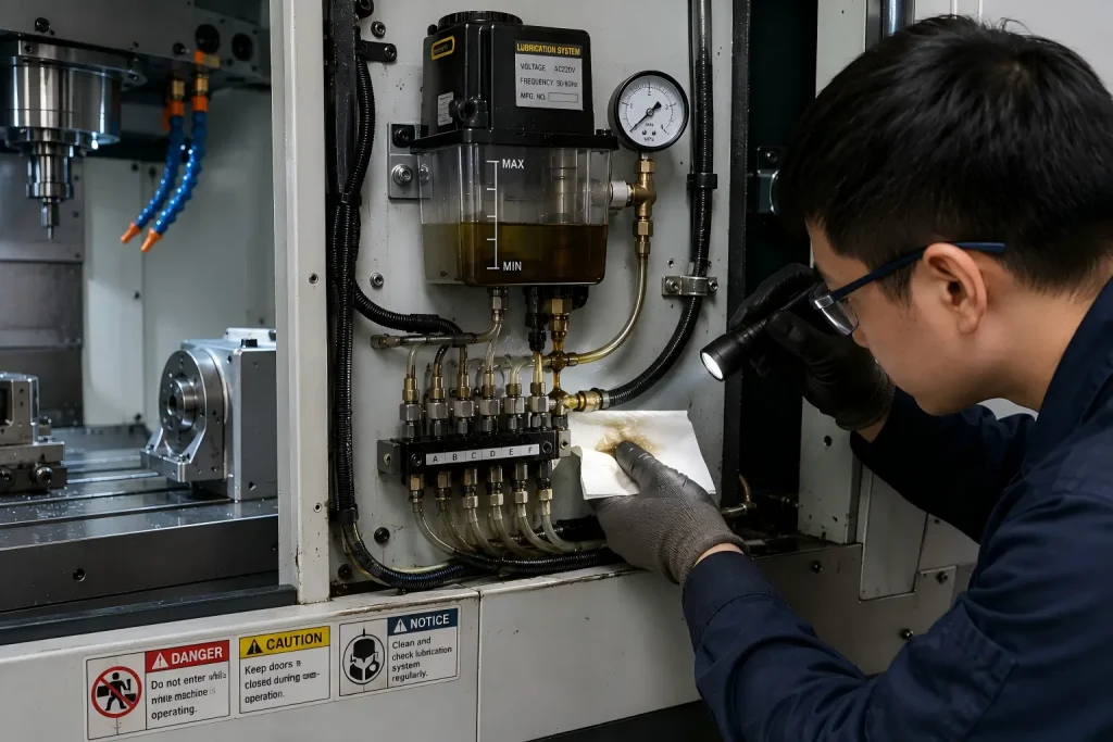
Common Causes of Oil Leakage
1. Loose Fittings, Damaged Tubes, or a Leaking Reservoir
Lubrication systems use pumps, reservoirs, flexible tubes, copper lines, tees, connectors, manifolds, and metering components.
Leakage may begin when:
- A fitting becomes loose
- A plastic tube cracks
- A copper line is damaged
- A hose is pinched or rubbed through
- A reservoir is cracked
- A reservoir gasket is incorrectly seated
- A connector is damaged during maintenance
- A replacement tube has the wrong size or routing
Oil may travel along a tube or machine casting before dripping at a lower point. The first visible drop may therefore be some distance from the actual failure.
2. Worn O-Rings, Seals, Gaskets, or Sealing Surfaces
Seals can lose effectiveness because of:
- Age
- Heat
- Abrasion
- Chemical incompatibility
- Contamination
- Incorrect installation
- Shaft or housing wear
- Misalignment
- Excessive pressure
- Damage during disassembly
Replacing only the seal may not solve the problem when the shaft, housing, groove, fitting, or sealing surface is damaged.
3. Incorrect Installation or Maintenance
Leakage may begin immediately after service when:
- A gasket is twisted or pinched
- An O-ring is cut
- A fitting is cross-threaded
- The wrong seal size is installed
- Mating surfaces are dirty
- Fasteners are tightened unevenly
- Tubing is not fully inserted
- A hose is routed against a sharp edge
- The reservoir is installed incorrectly
Use the machine manufacturer’s torque, seal, tubing, refill, and assembly procedures rather than applying one universal rule.
4. Overfilling, Incorrect Pressure, or Valve Problems
Too much lubricant or incorrect system pressure can force fluid past a weak seal or connection.
Possible causes include:
- Reservoir overfilling
- Incorrect refill procedure
- Faulty pressure regulator
- Stuck check valve
- Faulty relief valve
- Incorrect air pressure to the lubrication unit
- Metering component failure
- Incorrect lubricant viscosity
An unusually rapid pressure drop may indicate an external leak or another loss of system pressure. A system that cannot build pressure may also have an empty reservoir, air in the line, a pump problem, or an open connection.
SKF notes that excessive lubricant filling can force excess lubricant through seals, while Haas uses pressure build-up and pressure-decay behavior to diagnose machine-tool lubrication faults.
5. Blocked Metering Units, Restrictors, or Lubrication Lines
A blockage does not always create a visible leak at the blocked point.
Depending on the system design, it may:
- Restrict lubricant delivery downstream
- Create abnormal upstream pressure
- Cause another connection to leak
- Trigger a low-lubrication alarm
- Starve a guide, ball screw, bearing, or spindle
- Produce uneven lubricant distribution
Blockages may be caused by contamination, degraded lubricant, damaged tubing, incompatible fluids, or debris introduced during maintenance.
Bijur Delimon’s troubleshooting procedure requires checking the pump supply, distributor outlets, and individual lines to isolate internal or downstream blockages.
6. Contaminated Oil or the Wrong Lubricant
Contamination can damage valves, seals, metering units, bearings, and small lubrication passages.
Possible contaminants include:
- Chips
- Dust
- Coolant
- Water
- Cleaning residue
- Degraded oil
- Seal fragments
- Mixed or incompatible lubricants
Do not mix lubricants unless the machine manufacturer confirms compatibility. The correct viscosity and formulation matter because centralized lubrication systems depend on controlled flow through small lines and metering devices.
Bijur Delimon identifies dirt as a frequent cause of valve failure and instructs users to operate with clean lubricant without mixing different fluids.
7. Vibration, Misalignment, or Worn Mechanical Components
Vibration and misalignment can loosen fittings, damage hoses, wear seal contact surfaces, and shorten seal life.
Possible underlying problems include:
- Worn bearings
- Shaft runout
- Misaligned housings
- Machine collision
- Loose mounting hardware
- Unbalanced rotating components
- Unsupported tubing
- Repeated hose movement
- Excessive vibration from cutting
SKF notes that shaft or housing misalignment can make seals rub, increasing temperature, noise, and seal damage.
How to Trace an Oil Leak in a CNC Machining Center
Step 1: Read the Alarm and Maintenance History
Check whether the leak appeared together with:
- Low-lube alarms
- Pressure alarms
- Spindle-temperature warnings
- Hydraulic alarms
- Recent refilling
- Hose replacement
- Preventive maintenance
- Machine collision
- Unusual vibration or noise
This information helps identify the affected system before parts are removed.
Step 2: Stop and Clean the Area
Stop the machine according to the manufacturer’s procedure.
Before opening pressurized lubrication or hydraulic components:
- Isolate the machine
- Release stored pressure
- Follow lockout procedures
- Use trained and authorized personnel
- Wear suitable protective equipment
Clean the wet area so that new leakage can be distinguished from old residue.
Step 3: Record Reservoir Levels
Mark or photograph the fluid levels before running another approved test.
Check:
- Axis-lubrication reservoir
- Spindle-lubrication reservoir
- Hydraulic tank
- Gearbox level
- Coolant tank
A falling level helps confirm which system is losing fluid.
Step 4: Trace the Highest Wet Point
Oil flows downward and may follow tubes, cables, guards, and machine castings.
Inspect from the highest wet point toward:
- Reservoirs
- Pumps
- Tubes
- Fittings
- Tees
- Manifolds
- Metering units
- Seals
- Housings
Do not assume that the lowest drip point is the failed component.
Step 5: Run Only the OEM-Approved Test
When permitted by the machine manufacturer, run the approved lubrication or pressure test while observing:
- Whether pressure builds
- How long pressure is maintained
- Whether pressure drops immediately
- Whether oil appears at a fitting
- Whether all lubrication points receive fluid
- Whether air is visible in transparent tubing
- Whether an alarm is generated
Do not loosen pressurized fittings while the system is operating.
Step 6: Repair the Root Cause
Replacing a seal is not enough when the real cause is:
- Misalignment
- Damaged sealing surface
- Excessive pressure
- Blocked line
- Contamination
- Incorrect tubing
- Vibration
- Overfilling
Correct the underlying problem before returning the machine to production.
Step 7: Verify Lubrication and Part Quality
After repair, confirm:
- Stable reservoir level
- Correct pressure behavior
- No active external leakage
- Lubricant delivery to required points
- No remaining alarms
- Normal spindle and axis temperature
- Normal noise and vibration
- Clean coolant and work area
Parts produced during the fault should be reviewed according to the duration and severity of the problem.
Haas recommends timed pressure testing and direct inspection of the lubrication system to identify leaks and insufficient delivery before spindle or axis damage occurs.
How Oil Leakage Can Affect CNC Production
A small leak does not automatically make every machined part defective. The effect depends on the fluid, leak location, duration, system pressure, and whether lubrication delivery has been reduced.
Possible production risks include:
Insufficient Lubrication
A leak or blocked distribution system may prevent enough lubricant from reaching:
- Linear guides
- Ball screws
- Bearings
- Spindle components
- Rotary axes
- Other moving interfaces
This may increase friction, heat, wear, noise, and positioning instability.
Coolant and Workpiece Contamination
Oil entering the coolant or machining area may cause:
- Oily residue on parts
- Smoke or odor
- Coolant instability
- Poor cleaning results
- Coating or adhesion problems
- Additional washing requirements
- Contaminated packaging
Machine Downtime
Production may stop while the supplier:
- Traces the source
- Orders seals or tubing
- Cleans the machine
- Repairs the system
- Rechecks lubrication delivery
- Inspects affected parts
Electrical and Safety Risk
Oil near electrical cabinets, motors, wiring, heaters, walkways, or hot surfaces may create equipment and personnel hazards.
Dimensional and Surface-Quality Risk
Dimensional accuracy may be affected when inadequate lubrication causes abnormal heat, vibration, stick-slip movement, spindle instability, or axis wear.
The effect is conditional. A small external seep that does not change pressure, flow, temperature, cleanliness, or machine movement may not affect the part.
Parts produced during a confirmed lubrication fault may require:
- Lot isolation
- Cleaning
- Visual inspection
- Critical-dimension inspection
- Surface-finish review
- First-piece or last-piece comparison
- Additional documentation
For critical dimensions and acceptance limits, review our CNC machining tolerances resource.
For parts requiring positional or geometric verification, review our CMM inspection guide for CNC machined parts.
When Should the Machine Be Stopped?
Stop the machine and arrange qualified inspection when:
- Oil is leaking rapidly
- The reservoir level is falling unexpectedly
- A low-lubrication or pressure alarm appears
- Pressure cannot build or hold
- The spindle becomes hot or noisy
- Axis movement becomes abnormal
- Oil reaches electrical equipment
- Oil creates a slipping hazard
- Smoke or a burning smell appears
- Hydraulic clamping pressure becomes unstable
- Coolant contamination suddenly increases
- The leak source cannot be identified
- A hose, tube, reservoir, or fitting is visibly damaged
A small stain should still be recorded and monitored, but production should not continue merely because the machine can still complete a cycle.
Machine-tool repair, electrical work, hydraulic repair, and opening of pressurized lubrication systems should be handled according to the manufacturer’s instructions by trained and authorized personnel.
Haas explicitly warns that mechanical and electrical service procedures should be performed only by qualified personnel with suitable training.
FAQ: CNC Machine Oil Leakage
What Are the Most Common Causes of Oil Leakage in CNC Machining Centers?
Common causes include loose fittings, cracked tubes, damaged hoses, worn O-rings or seals, leaking reservoirs, incorrect assembly, overfilling, abnormal pressure, blocked lubrication components, contamination, vibration, and misalignment.
The visible drip may be below the actual source because oil can travel along machine surfaces and tubing.
How Do You Find the Source of a CNC Oil Leak?
Clean the affected area, identify the fluid, record reservoir levels, trace the highest wet point, review alarms, and use only the machine manufacturer’s approved lubrication or pressure test.
Inspect pumps, reservoirs, tubes, fittings, manifolds, metering units, seals, and lubrication points.
Can a Blocked Lubrication Line Cause a Leak?
It can, depending on the lubrication-system design.
A blockage may create abnormal upstream pressure, cause another fitting to leak, prevent lubricant from reaching downstream components, or trigger a lubrication alarm.
Does an Oil Leak Always Affect CNC Machining Accuracy?
No.
A small external seep does not automatically change the dimensions of machined parts. Accuracy becomes a concern when lubricant delivery, temperature, vibration, axis movement, spindle condition, coolant cleanliness, or process stability is affected.
Is Oil in the Coolant Tank Always a Machine Leak?
No.
Some way oil may enter the coolant system during normal operation. However, a sudden increase in tramp oil, a falling reservoir level, smoke, odor, poor part cleanliness, or loss of lubrication pressure should be investigated.
Can Overfilling a Lubrication Reservoir Cause Leakage?
Yes.
Overfilling or using an incorrect refill procedure can force lubricant past a gasket, vent, seal, or weak connection. Follow the machine manufacturer’s specified fill level and assembly procedure.
Can an Operator Repair the Leak?
Operators may perform routine visual checks and manufacturer-approved maintenance within their training.
Opening electrical cabinets, hydraulic systems, pressurized lubrication lines, spindle components, or machine covers should be handled by qualified personnel following the machine’s service and safety procedures.
How Often Should a CNC Lubrication System Be Inspected?
Follow the schedule in the machine manufacturer’s maintenance manual.
Routine checks should normally include reservoir levels, alarms, pressure behavior, tubing, fittings, active leaks, coolant contamination, and unusual noise or temperature. There is no single inspection interval suitable for every machine and lubrication system.
Conclusion
Oil leakage in a CNC machining center is a symptom, not a complete diagnosis.
The source may be a loose fitting, cracked tube, worn seal, overfilled reservoir, incorrect pressure, blocked metering component, contamination, vibration, or a mechanical problem elsewhere in the machine.
A practical response should:
- Identify the fluid
- Trace the highest wet point
- Check reservoir levels
- Review alarms
- Inspect tubes, fittings, seals, and lubrication components
- Verify pressure and lubricant delivery
- Correct the root cause
- Recheck affected parts when necessary
A small seep does not automatically mean that every part is defective. The risk depends on whether the fault affected lubrication, heat, vibration, coolant cleanliness, machine movement, or inspection results.
Machine repair should be handled by qualified equipment-service personnel.
Review Your CNC Part Quality Requirements
For custom CNC parts, Rapid Efficient can review drawings, critical dimensions, surface-cleanliness requirements, inspection points, reports, quantity, and packaging requirements before quotation.
For custom metal and engineering-plastic components, review our CNC machining services.