Quick Answer: How Can CNC Tool Wear Be Reduced?
The main tool-wear patterns in CNC machining include flank wear, crater wear, built-up edge, notch wear, edge chipping, plastic deformation, coating flaking, and thermal cracking.
The correct prevention method depends on the visible wear pattern.
Common starting actions include:
- Reducing excessive cutting speed when heat-related wear develops
- Correcting feed and depth of cut rather than reducing every parameter
- Selecting a tool grade and geometry suited to the workpiece
- Reducing tool overhang and runout
- Improving fixture and machine stability
- Preventing chips from being cut again
- Delivering coolant or lubrication consistently
- Avoiding rubbing, dwelling, and unstable tool engagement
- Replacing the tool before wear causes dimensional drift or edge failure
A worn tool should not be diagnosed only by total cutting time. Examine where the damage appears, whether it is uniform, how the chips look, and whether surface finish, cutting force, sound, temperature, or part dimensions have changed.
Flank wear is often the most predictable wear pattern, while random chipping or catastrophic fracture usually indicates instability, overload, chip recutting, or an ignored earlier wear condition.
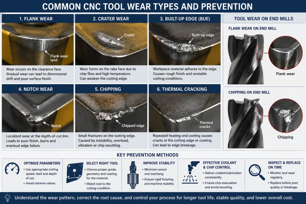
1. Common Tool-Wear Patterns in CNC Machining
Tool wear is the gradual deterioration of a cutting edge during contact with the workpiece and chip.
Some wear is expected. The objective is not to eliminate every visible wear mark, but to develop a predictable process in which the tool reaches a planned replacement point before it damages the part or fails unexpectedly.
Tool-Wear Diagnosis Table
| Wear Pattern | Where It Appears | Common Symptoms | Common Starting Actions |
|---|---|---|---|
| Flank wear | Clearance face along the cutting edge | Gradual dimensional drift, higher cutting force, dull edge, poor finish | Review cutting speed, grade, coolant delivery, and replacement interval |
| Crater wear | Rake face where the chip flows | A depression behind the edge, weakened edge, eventual breakage | Reduce excessive speed or heat, review grade, geometry, feed, and coolant |
| Built-up edge | Workpiece material attached to the cutting edge | Rough or torn finish, unstable dimensions, material periodically breaking away | Use sharper geometry, improve lubrication, adjust speed, and prevent rubbing |
| Notch wear | Localized area near the depth-of-cut line | Groove at one point, burrs, poor finish, local edge failure | Vary depth of cut, review grade and geometry, reduce rubbing and excessive heat |
| Chipping | Small irregular fractures along the edge | Sudden poor finish, noise, vibration, unpredictable tool life | Improve rigidity, shorten overhang, reduce runout, prevent chip recutting |
| Plastic deformation | Cutting edge becomes rounded, depressed, or displaced | Rapid loss of geometry, high force, dimensional error | Reduce heat and load, use a more deformation-resistant grade |
| Thermal cracking | Repeated cracks, often across the cutting edge | Comb-like cracks, edge fragments, sudden failure | Stabilize thermal conditions and review intermittent coolant application |
| Coating flaking | Coating separates from the substrate | Exposed substrate, accelerated wear, irregular edge condition | Review coating compatibility, edge preparation, adhesion, and cutting stability |
| Catastrophic fracture | Large part of the insert or tool breaks | Immediate tool failure, possible workpiece or machine damage | Stop and check overload, collision, stability, chip evacuation, and previous wear |
Flank Wear
Flank wear develops on the clearance face where the tool rubs against the newly machined surface.
Relatively uniform flank wear is usually more predictable than random chipping. However, rapid flank wear may indicate excessive cutting speed, an unsuitable grade, abrasive material, poor coolant delivery, or a worn coating.
Because the worn flank contacts the finished surface, it may gradually affect:
- Part diameter
- Surface finish
- Cutting force
- Heat
- Tool compensation
- Dimensional consistency
Crater Wear
Crater wear forms on the rake face where hot chips flow over the tool.
It is associated with heat, diffusion, chemical interaction, and abrasion. If the crater becomes too deep, the remaining cutting edge becomes weak and may chip or break.
Crater wear should not automatically be solved by reducing feed. Depending on the geometry, a feed that is too low may increase rubbing and contact time.
Built-Up Edge
Built-up edge occurs when workpiece material adheres to the cutting edge.
It is common with ductile or adhesive materials and may cause:
- Torn surfaces
- Burrs
- Unstable effective tool geometry
- Dimensional variation
- Edge damage when the deposited material breaks away
Built-up edge is not simply normal abrasive wear. It usually indicates an interaction between material adhesion, tool sharpness, cutting speed, lubrication, and chip flow.
Notch Wear
Notch wear is concentrated near the depth-of-cut line.
It can develop when the surface layer is harder or work-hardened, when scale or oxidation is present, or when the same point on the cutting edge repeatedly contacts the workpiece surface.
Changing the depth of cut between passes may help move the contact point rather than forcing the same area of the tool to carry every cut.
Chipping and Fracture
Chipping is usually less predictable than uniform wear.
Common causes include:
- Excessive runout
- Tool overhang
- Weak workholding
- Chatter
- Interrupted cuts
- Incorrect entry into the material
- Chips being recut
- An edge that is too sharp or too brittle for the load
- Excessive feed or depth of cut
- Collision
Complete fracture should be treated as a process failure rather than an acceptable tool-life endpoint.
Plastic Deformation and Thermal Cracking
Plastic deformation occurs when high cutting pressure and temperature cause the edge to lose its intended shape.
Thermal cracks can develop when a tool repeatedly heats and cools, especially in interrupted operations such as milling.
Coolant is not automatically the solution in every process. Inconsistent coolant delivery may create larger temperature cycles than stable dry cutting or consistent flood delivery.
Sandvik classifies flank wear, crater wear, built-up edge, notch wear and plastic deformation by their dominant wear mechanisms, while Seco also identifies chipping, coating flaking, thermal cracking and catastrophic fracture as distinct troubleshooting patterns.
2. What Causes Rapid or Unstable Tool Wear?
Cutting Speed
Cutting speed strongly affects cutting-zone temperature.
When speed is too high for the tool grade and material, it may accelerate:
- Flank wear
- Crater wear
- Plastic deformation
- Diffusion-related wear
- Coating breakdown
However, a cutting speed that is too low may also cause built-up edge, rubbing, unstable chip formation, or chatter.
The correct response depends on the observed wear pattern.
Feed and Depth of Cut
Feed and depth of cut control chip thickness and cutting load.
Excessive values may cause:
- Mechanical overload
- Chipping
- Deflection
- Poor chip evacuation
- Fixture movement
- Tool breakage
Values that are too low can also be harmful by causing:
- Rubbing instead of cutting
- Built-up edge
- Excessive contact time
- Work hardening
- Rapid wear concentrated in a small area
Do not reduce speed, feed, and depth of cut together without identifying the failure mechanism.
Tool Grade, Geometry, and Coating
Tool selection must match:
- Workpiece material
- Hardness
- Continuous or interrupted cutting
- Roughing or finishing
- Machine rigidity
- Tool overhang
- Coolant condition
- Production quantity
A harder, more wear-resistant grade may resist flank wear but chip under an unstable interrupted cut.
A tougher grade may resist chipping but wear faster under continuous abrasive cutting.
Tool coatings are also application-specific. TiN, TiCN, AlTiN, DLC, diamond, and uncoated polished tools should not be ranked using one universal list.
For a broader comparison of toughness, wear resistance, cutting speed, and tool cost, review our guide to high-speed steel vs carbide tools.
Runout, Overhang, and Rigidity
Excessive runout causes one cutting edge to remove more material than the others.
This can create:
- Uneven flute wear
- Chipping
- Vibration
- Poor surface finish
- Oversized or inconsistent features
- Short tool life
Long tool overhang reduces stiffness and increases deflection. Use the shortest practical tool and holder combination that still reaches the feature.
The fixture, spindle, holder, collet, insert seat, pull stud, and tool shank should all be checked when wear is uneven.
Haas identifies excessive runout, long gauge length, tool imbalance, damaged holders and inadequate fixture support as causes of vibration, poor finish and reduced tool life.
Chip Evacuation
Chips that remain in a pocket, bore, slot, or cutting zone can be cut a second time.
Chip recutting may cause:
- Edge chipping
- Flute damage
- Surface scratches
- Heat
- Tool loading
- Broken drills or end mills
Chip control depends on flute space, chip-breaker geometry, coolant or air delivery, toolpath, cutting direction, pocket depth, and workpiece material.
Coolant and Thermal Stability
Coolant can provide cooling, lubrication, and chip evacuation, but only when delivered consistently and matched to the process.
Problems may occur when:
- Coolant cannot reach the cutting edge
- Concentration is incorrect
- Flow is interrupted
- Nozzles move during production
- Chips block the coolant path
- Thermal cycling creates cracks
- Coolant is incompatible with the tool or workpiece
- Dirty coolant introduces abrasive particles
Flood coolant, through-tool coolant, MQL, air blast, and dry machining each have appropriate applications. None is universally best.
Workpiece Material and Condition
Material properties influence the likely wear pattern.
Important factors include:
- Hardness
- Abrasive inclusions
- Work hardening
- Thermal conductivity
- Chemical reactivity
- Scale or cast skin
- Heat-treatment condition
- Filler content in plastics or composites
- Material-lot variation
The tool should be selected from the exact grade and condition, not only from a broad label such as stainless steel, aluminum, titanium, or plastic.
3. How to Prevent Tool Wear in CNC Machining
Diagnose the Wear Pattern Before Changing Parameters
Do not begin by slowing the entire program.
First record:
- Which cutting edge is damaged
- Where the wear appears
- Whether the wear is uniform
- Cutting time or number of parts
- Tool number and offset history
- Workpiece material and lot
- Speed, feed, and depth of cut
- Tool overhang
- Coolant condition
- Chip shape
- Surface-finish changes
- Dimensional drift
- Abnormal sound or vibration
Photographs taken at regular tool-life intervals can help distinguish gradual wear from sudden failure.
Use a Stable Tool-Life Limit
The tool should be changed before it creates unacceptable parts or becomes likely to fracture.
A practical replacement rule may be based on:
- Maximum flank-wear width
- Number of parts
- Cutting time
- Dimensional compensation
- Surface roughness
- Burr formation
- Cutting-force trend
- Spindle-load trend
- Tool inspection
Do not copy one universal wear limit into every process. The acceptable point depends on tool type, feature, tolerance, finish and failure consequences.
Match Tool Grade to Stability
Use a tougher grade when the operation includes:
- Interrupted cutting
- Vibration
- Variable stock
- Heavy chip load
- Hard inclusions
- Unstable entry and exit
Use a more wear-resistant grade when the cut is stable but normal wear develops too quickly.
The grade, coating, substrate and edge preparation should be selected together.
Improve Toolholding and Workholding
Check:
- Spindle taper cleanliness
- Toolholder condition
- Collet wear
- Insert-seat damage
- Pull-stud condition
- Tool runout
- Tool balance
- Tool overhang
- Fixture support
- Clamping force
- Workpiece movement
A new cutting tool cannot correct a damaged holder, dirty taper, weak fixture, or worn spindle component.
Control Tool Engagement
Toolpaths should avoid abrupt and repeated changes in cutter load.
Useful controls may include:
- Consistent radial engagement
- Suitable lead-in and lead-out movements
- Reduced engagement in internal corners
- Separate roughing and finishing
- Avoiding repeated dwell
- Moving the depth-of-cut line between passes
- Keeping the cutter engaged where appropriate
- Preventing chips from being recut
Stabilize Coolant and Chip Removal
Confirm:
- Correct coolant type and concentration
- Stable nozzle position
- Sufficient flow
- Clear through-tool passages
- Functional filtration
- Effective chip evacuation
- No sudden wet-to-dry thermal cycling
- Clean cutting zone before the next pass
For some milling applications, consistent dry cutting may be more stable than intermittent coolant. Follow the tool and machine supplier’s recommendations for the actual process.
Monitor the Process, Not Only the Tool
Possible monitoring signals include:
- Spindle load
- Cutting force
- Vibration
- Acoustic changes
- Tool offset
- Part dimensions
- Surface finish
- Burr size
- Cycle-time changes
- Chip color and shape
Monitoring should support scheduled inspection rather than create unsupported claims that sensors can always predict failure.
4. Tool-Wear Risks for Different Workpiece Materials
Aluminum Alloys
Common problems include:
- Built-up edge
- Material adhesion
- Burrs
- Flute loading
- Scratching from uncontrolled chips
- Chipping when chips are recut
Useful starting controls include sharp cutting edges, polished flutes, adequate chip space, effective air or coolant delivery, and suitable cutting speed.
Filled or high-silicon aluminum materials may be more abrasive than common wrought grades and can require different tool materials or coatings.
Stainless Steel
Austenitic stainless steels can create:
- Built-up edge
- Notch wear
- Work-hardened surfaces
- High cutting force
- Long or difficult chips
Avoid rubbing and repeated light passes over work-hardened material. Use stable feed, suitable chip-breaker geometry, rigid tooling, and controlled coolant delivery.
Cast Iron
Cast iron may produce abrasive flank wear because of its microstructure, hard constituents, or cast skin.
Tool-grade selection, stable cutting conditions, dust or chip control, and surface-condition review are important.
Titanium and Nickel-Based Superalloys
Common problems include:
- Notch wear
- Crater wear
- Plastic deformation
- Edge chipping
- Heat concentrated near the tool
- Rapid wear at the depth-of-cut line
Use rigid workholding, short overhang, suitable carbide grade, controlled engagement, effective coolant delivery, and planned tool replacement.
For more information about why tungsten, Inconel, titanium, hardened steel, carbide, and ceramics require different processes, review our hardest materials to CNC machine guide.
Hardened Steel
Hardened steel may require coated carbide, ceramic, cermet, CBN, or grinding, depending on hardness, operation and cut stability.
Common risks include:
- Flank wear
- Crater wear
- Plastic deformation
- Chipping during interrupted cuts
- Surface-integrity damage
Do not choose CBN or ceramic tools only from the material name. Confirm hardness, stock allowance, continuity of the cut, finish and fixture stability.
Engineering Plastics and Reinforced Materials
Unfilled plastics may create smearing, heat, burrs, or elastic recovery.
Glass-filled and carbon-filled plastics can be highly abrasive and may accelerate flank wear.
Confirm the filler, exact grade, tool geometry, heat control, clamping and required surface condition.
Sandvik identifies different dominant wear mechanisms for steels, stainless steels, cast iron, titanium, heat-resistant superalloys and hardened materials; the tool grade and geometry should therefore be selected for the exact material group and cutting condition.
Tool-Wear Troubleshooting Checklist
| Observed Problem | Check First | Possible Adjustment |
|---|---|---|
| Uniform wear develops too quickly | Cutting speed, grade, material abrasiveness, coolant delivery | Reduce excessive speed or use a more wear-resistant grade |
| Built-up edge and torn surface | Tool sharpness, speed, lubrication, tool coating | Use sharper geometry, improve lubrication, and adjust speed |
| Chipping on one flute only | Runout, holder, collet, tool balance, insert seat | Correct runout and inspect the complete tool assembly |
| Random chipping on several edges | Fixture rigidity, chatter, chip recutting, tool overhang | Shorten overhang, improve support, and clear chips |
| Notch at the depth-of-cut line | Work-hardened layer, scale, repeated depth, unsuitable grade | Vary depth of cut and review grade and engagement |
| Crater behind the cutting edge | Cutting temperature, speed, grade, chip flow | Reduce excessive heat and choose a suitable grade or geometry |
| Thermal cracks | Interrupted cutting and unstable coolant delivery | Stabilize thermal conditions and coolant strategy |
| Plastic deformation | Excessive temperature or cutting load | Reduce heat and load or use a more deformation-resistant grade |
| Dimensional drift without obvious fracture | Flank wear, tool deflection, thermal movement, compensation | Establish a replacement point and verify offsets |
| Sudden complete failure | Collision, overload, severe chatter, blocked chips, ignored wear | Stop the process and investigate before installing a new tool |
How Tool Wear Affects CNC Part Cost and Quality
Buyers normally do not specify cutting parameters, but drawing and RFQ requirements can strongly influence tool wear.
For a wider review of setup count, tooling, material, tolerance, inspection, cycle time, and lead time, see our CNC turning and milling efficiency guide.
High-risk features may include:
- Deep narrow pockets
- Long-reach surfaces
- Small internal corner radii
- Deep holes
- Thin walls
- Interrupted features
- Hard scale or inconsistent stock
- Tight tolerances applied to every dimension
- Very low surface-roughness requirements
- Abrasive filled plastics
- Hardened materials
- Difficult burr requirements
Additional tool changes, finishing passes, inspection and rejected parts may increase the finished-part cost even when raw material is inexpensive.
Before quotation, provide:
| RFQ Item | What to Specify | Why It Matters |
|---|---|---|
| Material | Exact grade, condition, hardness, and filler | Controls tool selection and expected wear |
| Stock form | Plate, bar, casting, forging, extrusion, or molded blank | Surface condition and allowance affect wear |
| Quantity | Prototype and repeat volume | Determines tooling and replacement strategy |
| Critical dimensions | Fits, holes, bores, datums, and mating features | Identifies where tool-wear drift matters most |
| Surface finish | Required roughness and cosmetic faces | May require dedicated finishing tools |
| Burr requirement | Standard deburring or controlled edge condition | Difficult burr limits can change tooling |
| Inspection | Standard inspection, CMM, roughness, or full report | Defines when dimensional drift must be detected |
| Delivery requirement | Standard or urgent | Influences backup-tool and production planning |
Rapid Efficient can review the drawing, material, feature access, tolerances, finish, inspection requirements and quantity before quotation.
FAQ: CNC Tool Wear and Prevention
What Is the Most Common Type of Tool Wear?
Flank wear is one of the most common and predictable wear patterns. It develops along the clearance face and may gradually affect tool size, cutting force, surface finish and part dimensions.
Is Built-Up Edge a Type of Tool Wear?
Built-up edge is more accurately described as workpiece material adhering to the cutting edge.
It can change the effective geometry, damage the surface and pull away small fragments of the tool when it breaks off.
Does Higher Cutting Speed Always Increase Tool Wear?
Not always in the same way.
Excessive speed commonly accelerates heat-related flank wear, crater wear and plastic deformation. A speed that is too low may cause built-up edge, rubbing or chatter.
Should Feed Be Reduced When a Tool Wears Quickly?
Not automatically.
An excessive feed may overload the edge, but a feed that is too low may cause rubbing, work hardening or excessive contact time. Diagnose the wear pattern before changing the feed.
What Causes Carbide Tools to Chip?
Common causes include runout, vibration, unstable workholding, excessive overhang, interrupted cutting, unsuitable grade, incorrect entry, chip recutting and mechanical overload.
Can Coolant Cause Tool Damage?
Yes, when delivery is intermittent or incompatible with the process.
Repeated heating and cooling can contribute to thermal cracking. Coolant concentration, flow, nozzle position, filtration and through-tool passages should be checked.
When Should a Cutting Tool Be Replaced?
Replace it before wear causes unacceptable dimensions, finish, burrs, cutting force or fracture risk.
The replacement point should be defined for the specific tool, material, feature and inspection requirement.
How Does Tool Wear Affect CNC Part Tolerance?
Flank wear, chipping, built-up edge, tool deflection and thermal movement can change the effective cutting geometry.
The result may be gradual dimensional drift, sudden size changes or inconsistent surface finish.
Conclusion
Tool wear cannot be prevented by one universal cutting speed, coating or coolant strategy.
The correct action depends on the observed failure pattern:
- Uniform flank wear requires a different response from random chipping.
- Built-up edge requires a different response from crater wear.
- Thermal cracking requires a different response from mechanical overload.
- Abrasive filled plastic requires a different tool strategy from ductile aluminum or work-hardening stainless steel.
A stable process should combine:
- Suitable tool grade and geometry
- Controlled speed, feed and depth of cut
- Low runout
- Short practical tool overhang
- Rigid workholding
- Stable tool engagement
- Effective chip evacuation
- Consistent coolant or lubrication
- Planned tool inspection
- A defined replacement point
The goal is not maximum tool life at any cost. The goal is predictable tool life, acceptable part quality and the lowest practical cost per accepted part.
For custom housings, brackets, plates, slots, pockets, holes and multi-surface components, review our CNC milling services.
Review Your CNC Machining Project
Rapid Efficient can review your drawing, material, geometry, tool access, tolerances, surface-finish requirements, inspection needs and order quantity before quotation.
For custom housings, brackets, plates, slots, pockets, holes and multi-surface components, review our CNC milling services.