Climb milling and conventional milling are not just two textbook milling terms.
They change how the cutter enters the material, how chip thickness grows, where cutting force pushes the part, where burrs form, and why one surface may look clean while another edge becomes difficult to deburr.
For simple parts, the difference may not matter much.
For thin walls, slots, stainless steel, copper, cosmetic surfaces, sealing faces, or tight datum-related features, cutting direction can affect the final part more than buyers expect.
A drawing may only show dimensions.
The CNC process still needs to decide:
Should the cutter pull into the material, or push against it?
That choice can influence surface finish, burr direction, tool wear, fixture stability, and inspection results.
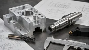
Rapid Efficient supports custom CNC milling projects for prototypes, low-volume parts, and production requirements. Before quotation, we review part geometry, material behavior, thin-wall areas, burr-sensitive edges, tolerance requirements, surface finish, inspection method, and delivery schedule.
The 60-Second Difference
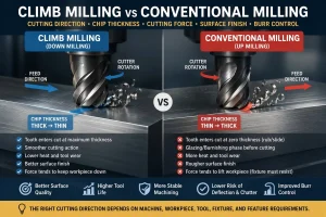
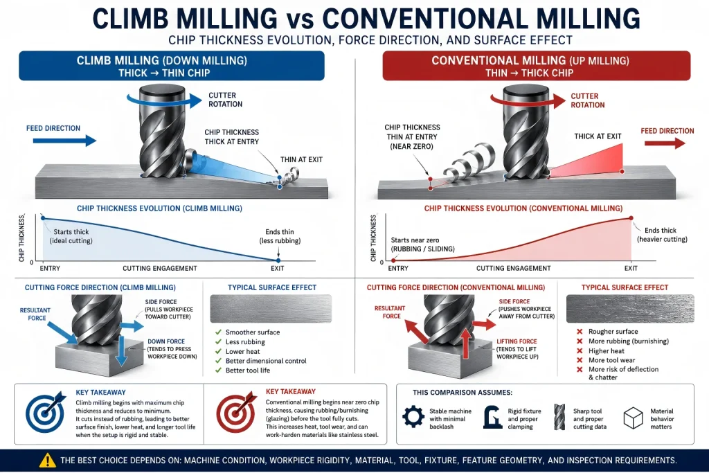
In climb milling, cutter rotation moves in the same direction as the feed at the cutting point.
In conventional milling, cutter rotation moves against the feed direction at the cutting point.
The difference sounds small.
It is not.
In climb milling, the chip usually starts thick and becomes thinner as the cutting tooth exits the material.
In conventional milling, the chip usually starts thin and becomes thicker as the cutting tooth exits.
That chip-thickness pattern changes the entire cut.
Climb milling often cuts more cleanly at the beginning of the tooth engagement.
Conventional milling often rubs before the tooth fully bites.
This is why climb milling is commonly preferred on modern CNC machines when the setup is rigid and backlash is controlled.
But climb milling also tends to pull the tool and workpiece together.
If the machine, tool, or fixture is not stable, that pulling action can create tool grab, vibration, or dimensional variation.
Chip Thickness Is the Real Difference
The most important difference between climb milling and conventional milling is chip thickness.
A milling cutter tooth should cut, not rub.
When the chip starts too thin, the edge may slide on the material before forming a real chip. That rubbing creates heat, tool wear, surface smearing, and work-hardening risk in certain materials.
In conventional milling, this first-contact stage is the dangerous part.
Before the cutting edge fully bites into the material, it can slide across the surface and create a short glazing or burnishing phase. On easy materials, this may only reduce tool life or leave a rougher finish. On 304 or 316 stainless steel, that rubbing can locally work-harden the surface before the next tooth enters the cut.
The next cutting edge is then no longer cutting the original surface.
It may be cutting a thin, hardened skin created by the previous rubbing pass.
This is why conventional milling can become risky when the part involves stainless steel, finishing passes, low chip load, dull tools, repeated light cuts, or programmed pauses.
For these parts, the machining plan should avoid rubbing and maintain real shearing action instead of polishing the surface before cutting it.
In climb milling, the cutter tooth usually enters with a thicker chip. This helps the tool cut sooner instead of rubbing first.
That can improve:
- Surface finish
- Tool life
- Heat control
- Burr control
- Work-hardening resistance
- Built-up edge control
- Finishing-pass stability
But this only works when the machine and fixture are stable enough to control the cutting force.
A poor setup can turn climb milling from a clean finishing method into a tool-grabbing problem.
Why Climb Milling Usually Gives a Cleaner Finish
Climb milling is common on modern CNC machining centers because it often creates a cleaner surface.
The cutting edge enters the material with enough chip load to shear material more efficiently. Less rubbing usually means less heat and less surface tearing.
This is especially useful when machining:
- Visible faces
- Flat sealing surfaces
- Sliding surfaces
- Datum faces
- Aluminum cosmetic parts
- Stainless steel finishing passes
- Copper parts sensitive to smearing
- Thin edges that need controlled burrs
Climb milling can also help keep the cutting edge sharper for longer because the tool spends less time rubbing before cutting.
However, climb milling is not automatically correct.
It still depends on:
- Tool sharpness
- Cutter diameter
- Feed per tooth
- Radial engagement
- Tool runout
- Fixture rigidity
- Machine backlash control
- Material behavior
- Wall thickness
- Final inspection requirement
A climb-milled surface can still fail if the tool is worn, the part vibrates, or the finishing allowance is poorly planned.
For surface finish options such as polishing, bead blasting, anodizing, passivation, and cosmetic review, see our CNC surface finishes guide.
Why Conventional Milling Still Exists
Conventional milling is not useless.
It can still be useful when the setup or cutting condition makes tool pull-in risky.
Because conventional milling pushes against the feed direction, it may be reviewed when:
- Machine backlash is a concern
- The setup is less rigid
- The surface has scale or hard skin
- The cutter is entering an interrupted surface
- The workpiece may move under pulling force
- Roughing is needed before a separate finishing pass
- Burr direction needs to be moved away from a critical edge
This is especially relevant on older manual machines or less rigid setups.
On a modern CNC machine, conventional milling may still appear in roughing, edge-control, or special feature strategies.
The key is intention.
Conventional milling should be chosen because it solves a specific force, burr, or setup problem.
It should not be used blindly just because it feels safer.
Backlash Is the Reason Old Advice Still Exists
Many old machining rules warn against climb milling.
That advice came from machines with backlash or less precise feed control.
If a machine has backlash, climb milling can pull the table or workpiece into the cutter. The result can be a sudden bite, chatter, broken tool, damaged surface, or dimension error.
Modern CNC machines usually control backlash much better.
That is why climb milling is common in CNC production.
Still, the old warning is not meaningless.
Backlash is not the only stability issue.
Even on a CNC machine, climb milling can become risky if:
- The part is poorly clamped
- The fixture is weak
- The tool is too long
- The wall is thin
- The cut engagement is too aggressive
- The material grabs the tool
- The setup lacks rigidity
- Chip evacuation is poor
A CNC strategy should not ask only whether the machine can climb mill.
It should ask whether this part, tool, fixture, and material can control climb milling forces safely.
Cutting Direction Failure Map
| Failure Mode | Why It Happens | More Likely When… | Process Control |
|---|---|---|---|
| Tool grabs the part | Climb milling pulls the cutter into the workpiece | Backlash, weak fixture, high engagement, flexible part | Reduce engagement, improve clamping, review toolpath direction |
| Surface looks rubbed or smeared | Cutter edge slides before forming a clean chip | Conventional milling, dull tool, low chip load, soft material | Use sharper tool, adjust feed, consider climb finishing |
| Stainless surface work hardens | Conventional milling creates rubbing or burnishing before full chip formation | 304/316 stainless steel, light finishing cuts, repeated passes | Maintain chip load, avoid dwell, protect the shearing zone |
| Burr appears on critical edge | Exit direction pushes material toward functional edge | Poor cutter exit planning, thin edge, ductile material | Plan burr direction, add edge break, review deburring access |
| Thin wall deflects | Cutting force pushes, pulls, or vibrates the wall during milling | Tall walls, deep pockets, low stiffness, aggressive passes | Add support, leave finishing stock, control final pass direction |
| Thin plate lifts from fixture | Cutting force is not resisted by fixture support | Thin floors, vacuum fixtures, large open pockets, weak clamping | Improve support, review force direction, inspect flatness after unclamping |
| Copper smears | Material sticks or rolls at the cutting edge | Dull tool, poor chip evacuation, unsuitable tool geometry | Use sharp tooling, reduce friction, improve chip evacuation |
| Slot width drifts | Tool deflects differently on each wall | Deep slots, slender tools, full slotting, chip packing | Rough first, leave allowance, finish each wall separately |
| Cosmetic surface shows tool marks | Final pass does not protect visible surface | Worn tool, wrong step-over, vibration, poor finish direction | Define cosmetic faces, control finishing pass, inspect surface |
| Datum face becomes unreliable | Milling force distorts or marks an inspection surface | Thin parts, poor sequence, rough datum strategy | Machine datums intentionally, protect inspection faces |
| Deburring changes dimensions | Burr removal affects hole, slot, or edge size | Small features, internal burrs, sharp tolerance limits | Define edge breaks and inspect after deburring |
This map is not a rule that says climb milling is always better.
It shows where cutting direction can create a quality failure if the process is not planned around the part.
Burr Direction Is Often the Hidden Issue
Many buyers focus on the machined surface.
The failed feature may be the edge.
Milling direction can affect where burrs appear and which side becomes harder to clean.
This matters when the part includes:
- Slot edges
- Hole intersections
- Thread entrances
- Sealing edges
- Cosmetic outer edges
- Thin ribs
- Mating faces
- Dowel-pin locations
- Electrical contact surfaces
- Post-finish visible surfaces
A burr on an outside edge may be easy to remove.
A burr inside a slot or near a thread entrance may be much harder to control.
A burr on a sealing edge may create leakage risk.
A burr on a visible anodized or passivated surface may become more obvious after finishing.
The safer question is not only:
Which milling direction gives the best finish?
It is:
Where will the burr go, and can that edge be deburred without damaging the part?
Thin Walls and Slots Change the Answer
Thin walls make climb milling and conventional milling more sensitive.
Cutting force direction does not only affect the side wall.
It can also affect whether a thin plate, thin floor, or weakly supported workpiece stays seated against the fixture.
In climb milling, the force pattern often helps keep the cutting edge engaged and can help hold the workpiece more firmly against the support when the setup is rigid.
In conventional milling, the force pattern can create a lifting tendency that the fixture must resist. This becomes important for large thin plates, thin-bottom pocket parts, vacuum-fixtured parts, lightly clamped parts, or parts with large open areas after roughing.
If the workpiece lifts away from the datum surface, the result may be:
- Chatter
- Gouging
- Uneven floor thickness
- Poor flatness
- Slot-width variation
- Surface tearing
- Loss of datum control
- Inspection failure after unclamping
For thin plates and thin-bottom parts, the process should review not only climb vs conventional direction, but also fixture support, vacuum holding area, clamp position, roughing sequence, remaining material, finishing stock, and final inspection method.
The practical question is:
Will the cutting force keep the part seated, or will it try to lift the feature away from the datum?
A thick block may stay stable under either method.
A thin wall may move, vibrate, or spring back after cutting.
In climb milling, the cutting action may pull the wall or tool into the cut.
In conventional milling, the force direction changes, but rubbing and heat may increase.
Neither method is automatically safe.
Thin-wall milling should review:
- Wall thickness
- Wall height
- Tool diameter
- Tool overhang
- Radial depth of cut
- Axial depth of cut
- Fixture support
- Roughing sequence
- Finishing allowance
- Final pass direction
- Inspection method
Slots also need special care.
Full slotting is a special case.
When an end mill cuts a full-width slot with radial engagement close to the cutter diameter, the tool is not performing a clean one-sided climb or conventional pass. One side of the cutter behaves like climb milling, while the other side behaves like conventional milling.
That means two different chip-formation patterns and force directions can exist at the same time inside the same slot.
This can create:
- Uneven side-wall finish
- Radial tool deflection
- Chip packing
- Width variation
- Chatter
- Tapered or non-parallel slot walls
- Burrs on both sides of the slot
- Higher risk on deep or narrow slots
For high-precision slots, a safer route is often not to finish the slot in one full-width cut.
A more controlled strategy may include roughing the slot with allowance, then using separate side-finishing passes to clean each wall. When the setup allows, climb finishing passes on each side can help improve side-wall quality and reduce uncontrolled tool deflection.
This is especially important when the slot controls fit, sliding motion, sealing, alignment, or datum-related inspection.
When milling a slot, both walls may be affected by tool deflection, chip packing, and cutter engagement. One side may look better than the other. Width can drift even when the surface looks acceptable.
For thin walls, small slots, deep pockets, chamfers, and manufacturability review, see our CNC machining design guide.
Material Behavior Changes the Choice
The same milling direction can behave differently across materials.
Aluminum
Aluminum often responds well to climb milling on stable CNC equipment.
The main risks are built-up edge, burrs, tool marks, and cosmetic damage after anodizing.
For aluminum parts, cutter sharpness, chip evacuation, and deburring access are often more important than buyers expect.
Stainless Steel
Stainless steel can work harden when the tool rubs.
Climb milling may help reduce rubbing during stable finishing passes, but stainless steel still needs correct chip load, coolant delivery, tool geometry, and tool wear control.
If the tool only skims the surface, both climb and conventional milling can create problems.
Copper
Copper is ductile and can smear when the cutting edge is not sharp or chip evacuation is poor.
Climb milling may improve shearing action in some finishing conditions, but copper still requires careful tool selection and handling to avoid burrs and surface tearing.
Brass
Brass is often easier to machine than copper and may produce cleaner chips.
Even so, cutter direction still affects burrs around holes, slots, threads, and cosmetic edges.
Engineering Plastics
Plastics may deflect, melt, or leave fuzzy edges if heat and tool geometry are not controlled.
For plastics, milling direction should be reviewed together with support, cutting temperature, wall thickness, and dimensional stability after machining.
For material-specific machining risks, review our CNC machining materials guide.
How Buyers Should Mark Critical Edges on the Drawing
Buyers do not need to specify every climb or conventional milling pass.
That is the machining supplier’s process decision.
But buyers should identify which surfaces and edges matter.
Useful drawing notes include:
- “This face is cosmetic.”
- “This edge contacts a seal.”
- “No burrs allowed inside this slot.”
- “Do not round this locating edge.”
- “This face is used as a datum.”
- “This wall is thin and must not deform.”
- “This surface slides against another component.”
- “Final dimensions apply after surface treatment.”
- “CMM report required for marked critical features.”
These notes help the machining team choose the safer milling direction, finishing sequence, deburring route, and inspection method.
A small note on a drawing can prevent a large argument after production.
For tolerance planning, datum-related features, and inspection limits, review our CNC machining tolerances guide.
Inspection Confirms the Process Choice
The final part does not care whether the program used climb milling or conventional milling.
It only cares whether the surface, edge, slot, hole, and datum meet the drawing requirement.
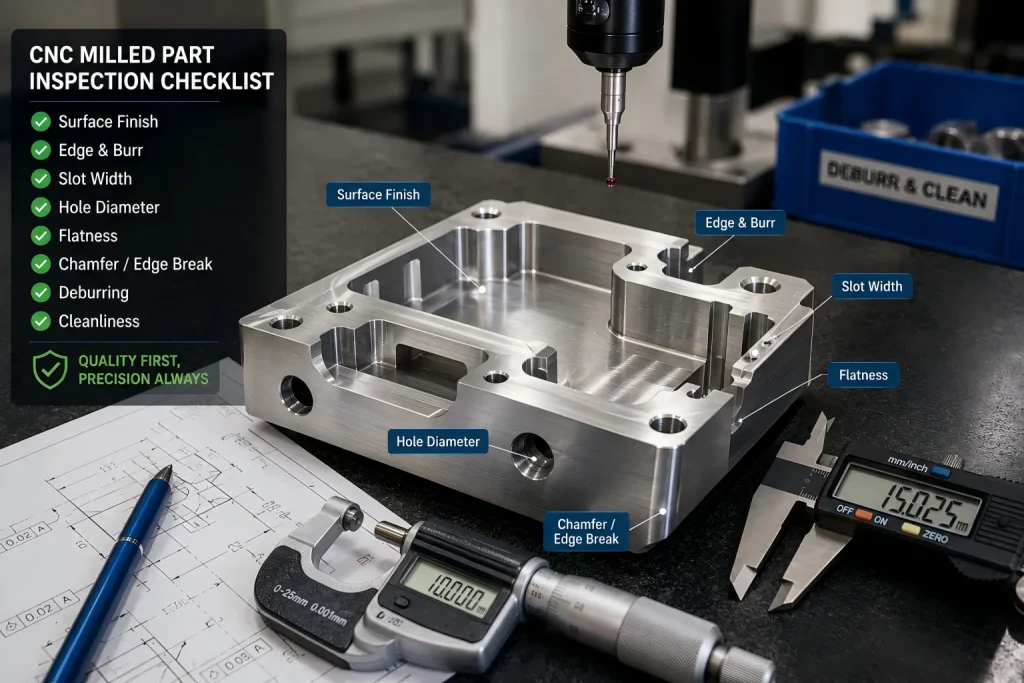
Inspection may include:
- Visual surface review
- Burr inspection
- Edge-break check
- Slot width measurement
- Flatness inspection
- Dimensional inspection
- Thread-gauge inspection
- Pin-gauge inspection
- CMM inspection for datum-related features
- Surface finish measurement when required
- Post-finish inspection after anodizing, plating, coating, or passivation
A milling strategy is successful only when the part passes functional and visual review.
For CMM reports, material certificates, inspection documentation, and shipment quality review, see our quality assurance process.
Shop-Floor Questions
Is climb milling always better on CNC machines?
No.
Climb milling is often preferred on modern CNC machines because it can improve surface finish and reduce rubbing, but it still depends on fixture rigidity, tool engagement, material behavior, machine condition, and feature geometry.
Why does conventional milling sometimes leave a worse finish?
In conventional milling, the chip usually starts thin. The cutting edge may rub or burnish the surface before forming a full chip. This can create heat, tool wear, surface smearing, and work-hardening risk in stainless steel.
That does not make conventional milling useless. It means it should be used when its force direction or roughing behavior solves a specific problem.
Does milling direction affect burrs?
Yes.
Cutting direction can move burr risk from one edge to another. This matters around slots, holes, threads, sealing edges, cosmetic faces, and burr-sensitive internal features.
Why is full slotting more difficult than side milling?
Full slotting makes both sides of the cutter engage the material. One side can behave more like climb milling while the other behaves more like conventional milling.
This can increase tool deflection, chip packing, width variation, and side-wall finish problems. Precision slots often need roughing allowance and separate finishing passes on each wall.
Should buyers specify climb milling or conventional milling on drawings?
Usually no.
Buyers should specify the functional surfaces, burr-sensitive edges, surface finish, tolerances, and inspection requirements. The machining supplier should choose the milling strategy that protects those requirements.
Upload Your Milling Part Drawing for Process Review
Send your 2D drawing, 3D CAD file, material grade, quantity, tolerance notes, thin-wall areas, burr-sensitive edges, surface finish requirements, inspection needs, and delivery target.
Our team will review milling strategy, cutting direction, burr-control risk, finishing sequence, inspection method, packaging needs, and delivery schedule before quotation.
CTA Button: Upload Your Drawing
About Rapid Efficient
Rapid Efficient supports custom CNC machining projects for prototypes, low-volume parts, and production requirements.
With 18 years of high-precision CNC machining experience, our team reviews material behavior, machining strategy, tolerance risks, post-processing requirements, inspection methods, packaging conditions, and delivery schedules before quotation.
Our available capabilities include 4-axis, 5-axis, and multi-axis CNC machining, together with inspection equipment such as CMM, projectors, and spectrometers.
Depending on the actual part and project requirements, machining accuracy down to 0.01 mm and inspection accuracy down to 0.001 mm are available.
Rapid Efficient has obtained ISO 9001 and ISO 14001 certification.