A milled wall can look square to its base and still fail a perpendicularity callout. A bore may have the correct diameter at its entrance while its derived axis tilts relative to the mounting face. In both cases, a quick 90-degree check can miss the characteristic that the drawing actually controls.
Perpendicularity in GD&T controls the orientation of a surface, axis, or another applicable derived feature relative to a referenced datum. The tolerance zone is oriented exactly 90 degrees to that datum, while the controlled feature is allowed to vary within the stated zone.
The tolerance value is normally a linear value, not an angular value. A callout of 0.05 mm perpendicularity does not mean 0.05 degrees. The meaning also changes according to whether the drawing controls an actual surface or the derived axis of a feature of size.
Perpendicularity does not by itself control feature size or location. A bore can meet perpendicularity and still be in the wrong position. A wall can satisfy its orientation requirement and still be outside a separate dimensional limit. Broader decisions about size, location, form, and datum-related controls should be coordinated through a realistic CNC machining tolerances guide.
Start With the Controlled Feature: Surface or Axis?
The first question is not “What is the perpendicularity value?” It is “What geometric element is being controlled?”
| Question | Surface Perpendicularity | Axis Perpendicularity |
|---|---|---|
| Controlled element | The actual surface | The derived axis or median line of a feature of size |
| Common function | Keep a wall, shoulder, or face square to a functional datum | Keep a bore, pin, boss, or shaft direction normal to a datum |
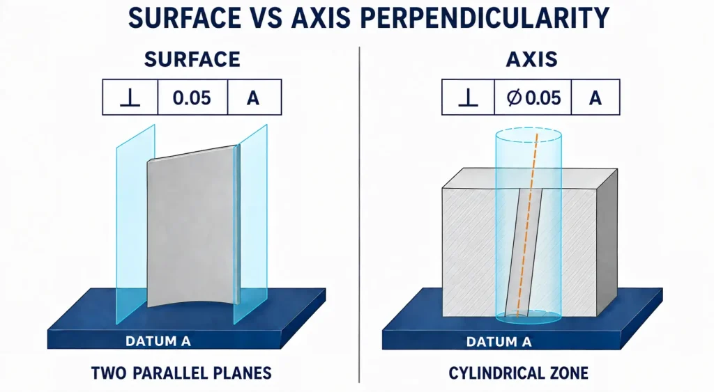
| Typical tolerance zone | Two parallel planes oriented 90 degrees to the referenced datum | A cylindrical zone when the diameter symbol is specified |
| Separate requirement still needed | Surface location, size, or another form requirement when function demands it | Feature size and position when assembly also depends on diameter and location |
| Common false check | Checking one edge or one height with a square | Checking only bore diameter or one circle near the entrance |
A surface callout requires the controlled surface to remain inside its tolerance zone. Local high points, taper, bow, or twist can therefore affect the result even when the average angle appears correct.
An axis callout applies to a feature of size, such as a bore or external cylindrical feature. The inspection system must first establish the feature from measured data and then evaluate its derived axis under the governing drawing rules. Measuring the diameter alone cannot prove the axis orientation.
A derived median plane may also be controlled for an applicable width feature. The callout attachment, feature context, symbols, modifiers, and title-block standard determine the correct interpretation.
Read the Tolerance Zone, Not Just the 90-Degree Relationship
The perpendicularity symbol is ⟂. It appears in the characteristic cell of the feature control frame, followed by the tolerance-zone information and the referenced datum or datum system.
For an illustrative surface callout written as ⟂ | 0.05 | A, the controlled surface must fit between two parallel planes separated by 0.05 mm and oriented 90 degrees to Datum A.
For an illustrative axis callout written as ⟂ | ⌀0.05 | A, the derived axis must remain inside a cylindrical tolerance zone 0.05 mm in diameter, oriented 90 degrees to Datum A.
These examples explain the general difference between planar and diametrical zones. The actual interpretation still depends on how the feature control frame is attached, the feature being controlled, any modifiers, and the standard identified on the drawing.
For an axis control applied to a feature of size, a material-condition modifier may change the permissible variation under the governing standard. Do not calculate additional or “bonus” tolerance until the feature size, modifier, datum references, and applicable standard have been confirmed. Do not assume that the same rule applies to a simple surface callout.
Why Linear and Angular Tolerances Are Not Interchangeable
An angular dimension such as 90° ± an angular tolerance controls an angle through an angular limit. A perpendicularity callout controls a linear tolerance zone. Converting one into the other requires the relevant feature length and does not automatically reproduce the same surface, datum, or inspection requirement.
This distinction matters on tall walls and long axes. A small angular change may create a larger linear deviation over a longer evaluated length, while a short feature may make the axis more sensitive to how measurement points are collected and fitted.
What Perpendicularity Does Not Control
Perpendicularity alone does not establish:
- The diameter of a bore or pin
- The location of a hole
- The distance from the controlled surface to another feature
- The flatness of an unrelated datum surface
- The complete rotational behavior of a face or diameter
A position, size, flatness, profile, or runout requirement may also be needed when the assembly function depends on those characteristics.
The geometry of the zone—not a visual estimate of squareness—defines acceptance.
The Datum Simulator Can Decide Whether the Result Passes
A datum is theoretically exact. The datum feature is the real surface, bore, width feature, or other feature identified on the part. Because the datum feature has form error, the manufacturing and inspection process must establish a practical representation of the required datum.
Depending on the drawing system and verification plan, that representation may be established physically by fixture contact or mathematically from measured data. A convenient CAD face, machine coordinate, table edge, or global fitted alignment is not automatically equivalent to the drawing datum.
For a planar primary datum, practical questions include:
- Which areas make contact with the simulator?
- Are chips, burrs, coating buildup, or surface damage affecting contact?
- Is the part freely supported or intentionally restrained?
- Does the CMM alignment reproduce the specified datum rather than an unrelated fitted alignment?
- Can the datum feature be accessed after all machining and finishing operations?
Primary, secondary, and tertiary references have different roles in constraining the part. A perpendicularity callout may need only the datum that establishes the required orientation. Additional datum references or separate location controls may be needed when the inspection alignment, feature location, or clocking must also be constrained. Perpendicularity itself does not locate the feature. The drawing—not shop convenience—sets the hierarchy.
For a deeper explanation of datum features, simulators, setup transfer, and inspection alignment, review the guide to types of CNC machining datums.
Flexible parts need special attention. A component that is forced flat during machining or measurement may move after the clamps are released. If function requires inspection in a free state or under a defined restraint, that condition should be agreed before quotation.
Why a Part Can Look Square and Still Fail
Several shortcuts can create a convincing but incomplete result.
Checking Only One Height on a Wall
An indicator reading near the bottom of a wall may look acceptable while the upper section leans, bows, or twists. Surface perpendicularity applies to the controlled surface defined by the callout, not only to one convenient line.
Checking Only the Entrance of a Bore
A bore entrance can be round and correctly sized while the bore tapers or its derived axis changes direction through depth. A single measured circle cannot establish the full bore axis when the drawing controls that axis.
Referencing the Wrong Face
A shop may check the controlled feature from an easy external face even though the drawing identifies a different mounting surface as Datum A. The measurement may be repeatable but still unrelated to assembly function.
Measuring Only While the Part Is Clamped
Clamping may pull a thin base or wall into the fixture. The part can appear perpendicular in the restrained condition and change after release. Neither condition is automatically correct; the drawing or inspection plan should identify the required state when the difference matters.
Treating a Square as Complete GD&T Verification
A precision square can support setup or comparative checks on accessible features. It does not automatically reproduce every datum rule, capture the full controlled surface, or evaluate a derived bore axis. It should not be treated as complete acceptance evidence unless the agreed method supports the drawing requirement.
Where CNC Setups Lose Perpendicularity
Programming a 90-degree toolpath does not make the finished part automatically perpendicular to its functional datum. The relationship depends on the complete chain from datum preparation to final inspection.
Datum Preparation Before the Controlled Feature
If the intended datum face is rough, bowed, damaged, or not fully seated, every later feature may inherit the setup error. Chips under the part, burrs around locating surfaces, uneven supports, or excessive clamp force can tilt or deform the workpiece.
Qualifying the datum early can help, but the process must preserve or transfer that reference through later operations.
Tall Side Walls and Long Tool Reach
Tall walls increase sensitivity to fixture tilt, machine geometry, tool deflection, vibration, and wall movement. A long end mill may cut more heavily near one level than another. Thin walls can also deflect during the cut and recover after the tool passes.
Depending on the geometry, the process may need shorter tool reach, staged finishing, improved support, balanced stock allowance, lighter finishing engagement, or inspection after release. These are review options, not universal settings.
Bore and Pin Axis Direction
Drill walk, an uneven entry surface, boring-bar deflection, interpolation error, tool runout, taper, and insufficient support may affect the direction of a bore or pin feature. A correct entrance diameter does not confirm that the derived axis remains normal to the mounting face.
Deep or recessed features may also limit probe access. Short bores create a different problem: the available axial span may be too limited for a stable axis evaluation, while probe-ball size and stylus geometry may further restrict where useful data can be collected. The result can become more sensitive to bore form, point distribution, and the fitting method, so the measurement strategy should be reviewed before acceptance.
Datum Transfer Between Setups
A base may be machined in one setup while a wall, shoulder, or bore is finished in another. Each transfer introduces possible error from fixture locators, soft jaws, probe alignment, rotary positioning, work offsets, contact contamination, and part distortion.
Machining functionally related features in one setup may reduce transfer risk where geometry and access permit. When separate setups are required, qualified transfer features and a final datum-based inspection plan should be established before production.
Heat Treatment, Coating, and Final Release
Heat treatment, stress release, aggressive material removal, or part release may change the final relationship. Coating can also affect datum contact and the surface evaluated during inspection. The drawing should state whether the requirement applies before or after the specified finish when that distinction affects function.
Perpendicularity Control and Inspection Matrix
| Controlled Feature | Functional Failure to Avoid | Main Machining Risk | Datum and Zone Review | Inspection Route to Review | Common False Pass |
|---|---|---|---|---|---|
| Tall milled wall relative to mounting base A | Interference, uneven seating, or misaligned assembly along wall height | Wall deflection, fixture tilt, long tool reach, datum seating error | Confirm the complete surface and planar zone relative to A | Datum simulation with an indicator sweep or CMM surface evaluation, depending on access and tolerance | Checking one edge or only the bottom of the wall |
| Bore axis relative to flange face A | Shaft, bearing, or mating component enters at an angle | Drill walk, boring deflection, taper, setup transfer | Confirm that the axis is controlled and whether a diametrical zone is specified | Multi-section bore measurement and axis evaluation; a qualified functional gauge may be reviewed when appropriate | Measuring only bore diameter or the entrance circle |
| External pin or boss axis relative to base A | Pin binds or enters a mating hole at an angle | Part tilt, turning/milling transfer, tool or spindle alignment error | Separate axis orientation from pin size and position | CMM axis evaluation or an agreed functional fixture | Passing the pin diameter and assuming the axis also passes |
| Shoulder or end face relative to datum axis A | Uneven axial seating or face contact | Face produced in a different setup from the datum feature | Confirm a surface zone oriented to the datum axis and whether rotational behavior is also functional | CMM or an agreed datum-axis simulator; review runout separately when rotation is the real requirement | Substituting an axial runout reading without confirming equivalence |
| Thin housing wall relative to mounting plane A | Released part changes orientation and no longer aligns in assembly | Clamp distortion, residual stress, insufficient support | Define free-state or restrained inspection and datum contact | Supported free-state inspection or specified restraint, with the condition reported | Measuring only while the part is forced against the fixture |
| Short or recessed bore axis relative to face A | Assembly axis is uncertain despite acceptable size | Limited cutting and probing access; insufficient evaluated length | Confirm the controlled axial extent and measurement strategy | Suitable stylus access, multiple levels where possible, or an agreed functional method | Constructing an axis from one circle or too little usable data |
The correct route depends on the controlled feature, tolerance, geometry, material behavior, access, and required acceptance evidence. The matrix is a planning tool, not a substitute for the governing drawing standard.
Choose the Inspection Method by the Controlled Feature
No single instrument is automatically correct for every perpendicularity callout.
| Inspection Method | Appropriate Use | What Must Be Controlled | Main Limitation |
|---|---|---|---|
| Surface plate with height gauge or indicator | Accessible surface relative to a physically simulated planar datum | Clean datum contact, stable support, indicator direction, sweep coverage, and part restraint | May miss inaccessible areas and may not reproduce a complex datum system |
| Precision square or comparator setup | Setup verification and comparative checks on accessible walls | Square calibration, datum seating, contact method, and evaluated height | A local comparison does not automatically evaluate the full GD&T zone |
| CMM surface evaluation | Planar or complex accessible surfaces with datum-based alignment | Datum construction, point distribution, stylus access, fitting method, and support state | Sparse points may miss local error; a convenient alignment may not match the drawing |
| CMM bore or pin-axis evaluation | Derived axis perpendicularity of a feature of size | Multiple measured sections, usable axial span, probe qualification, datum alignment, and evaluation settings | Deep, small, short, or obstructed features can restrict useful data |
| Qualified mandrel or functional gauge | Selected bore-axis or assembly-oriented checks | Gauge fit, clearance, insertion depth, datum interface, and acceptance rule | Clearance and gauge geometry can influence the result; it may provide attribute rather than variable data |
| In-machine probing | Setup confirmation and in-process correction | Probe calibration, machine condition, work offset, datum access, and part temperature | It does not automatically replace independent final inspection |
If the controlled feature is threaded, probing a few thread crests does not necessarily reproduce the functional thread axis. The inspection plan should define how the pitch-diameter-related axis will be simulated or evaluated. A qualified threaded gauge or locator mandrel may be appropriate for some functional checks, but its fit, clearance, engagement length, seating, and acceptance rule should be agreed before it is used as measurement evidence.
A CMM can evaluate surface and axis perpendicularity, but the result still depends on datum alignment, probing strategy, point coverage, feature fitting, support, and the reported inspection scope. The guide to CMM inspection for CNC machined parts explains what buyers should check beyond a simple PASS result.
When a measured value lies close to the tolerance boundary, measurement uncertainty and the agreed decision rule may affect conformity assessment. Report scope, sampling, and any customer-specific rule should therefore be confirmed before production rather than disputed after delivery.
The inspection plan should reproduce the drawing requirement, not merely produce a convenient number.
Use Perpendicularity When 90-Degree Orientation Is the Real Requirement
Perpendicularity is useful when the functional problem is orientation at 90 degrees to a datum. It is not the correct answer to every alignment problem.
| Functional Requirement | Control to Review |
|---|---|
| Keep a wall or face normal to a functional datum | Surface perpendicularity |
| Keep a bore, pin, or shaft axis normal to a datum | Axis perpendicularity, with the zone and feature-of-size rules defined |
| Keep a surface flat without referencing another feature | Flatness |
| Locate a hole or pin relative to datums | Position |
| Control a surface at an angle other than 90 degrees | Angularity or profile, depending on the design intent |
| Control rotational variation of a face or diameter | Circular or total runout, depending on the functional surface and extent |
| Control both orientation and location of a complex surface | Profile, with suitable datums and basic dimensions |
More than one control may be necessary. A precision bore may need a size limit, position tolerance, and perpendicularity requirement if diameter, location, and axis orientation each protect a different part of the assembly.
For a threaded hole, press-fit locator, or another feature that supports a protruding fastener or pin, controlling only the feature within the part may not protect clearance above the mounting surface. The designer should review whether a projected tolerance zone, position control, or another orientation requirement is appropriate under the governing drawing standard, and should define the required projection height from the functional interface. The projected-zone symbol should not be added as a default substitute for a complete assembly and tolerance analysis.
Do not add redundant controls automatically. If position or profile already provides the required orientation under the governing standard, an additional perpendicularity callout may increase drawing complexity without adding functional value. The designer should define the failure mode first and then select the control that protects it.
Drawing Information That Prevents Wrong Alignment
| Drawing Item | What to Define | Why It Matters |
|---|---|---|
| Governing standard | Standard name and applicable revision in the title block or specification | ASME and ISO practices should not be mixed by assumption |
| Controlled feature | Clear feature-control-frame attachment to the surface or feature of size | Prevents surface and axis interpretations from being confused |
| Datum reference | Datum feature letters and required precedence | Establishes the functional orientation and any required location or clocking |
| Tolerance-zone form | Linear value and diameter symbol when applicable | Distinguishes planar and cylindrical zones |
| Feature size and modifiers | Size limits and any applicable material-condition requirement | Keeps size, orientation, and any permitted variation correctly separated |
| Location requirement | Basic dimensions and position or profile control when needed | Perpendicularity alone does not locate the feature |
| Evaluated extent | Controlled surface, bore depth, axis extent, or limited area when specifically required | Prevents inspection of only a convenient local region |
| Part state | Free state, freely supported state, or defined restraint when relevant | Flexible parts may change after unclamping |
| Finishing state | Requirement before or after coating, heat treatment, or other finishing | Datum contact and final geometry may change through processing |
| Reporting scope | Required characteristics, sample quantity, raw data, and report format | A CMM report does not automatically include every drawing requirement |
Do not specify a CMM simply because a tolerance is tight. Specify the required characteristic and evidence. The supplier can then review whether a CMM, indicator setup, functional gauge, or combined inspection route is appropriate.
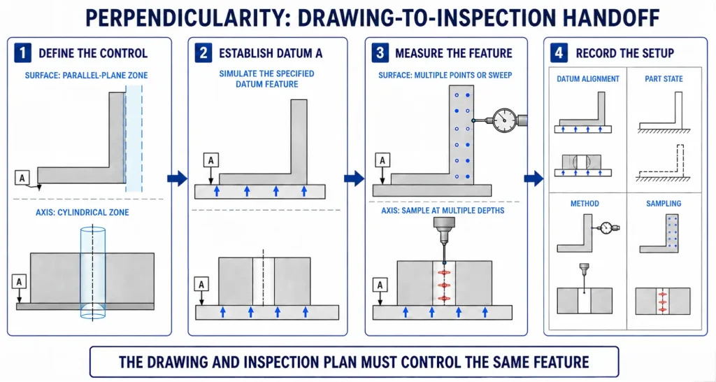
A complete callout lets the supplier plan machining and inspection from the same reference.
What Raises Perpendicularity Cost Before Quotation?
The tolerance value is only one cost driver. Cost may also rise when:
- A tall wall or long axis increases sensitivity to angular setup error
- A bore is deep, small, short, recessed, or difficult to probe
- The datum feature is flexible, interrupted, rough, or unavailable in an early setup
- The controlled feature and datum must be produced in separate operations
- Custom support, soft jaws, datum simulators, or functional gauges are required
- Heat treatment or finishing requires final reinspection
- A detailed CMM program, expanded point coverage, or special stylus configuration is needed
- Free-state and restrained results must both be evaluated
- Full reporting or a larger inspection sample is requested
A supplier should confirm the controlled feature, datum hierarchy, feature height or depth, machining access, part rigidity, finish state, and inspection scope before accepting a demanding perpendicularity requirement.
Send the Evidence Needed for a Perpendicularity Review
For a useful review, provide:
- The current 2D drawing and 3D CAD model
- The drawing standard and revision
- The controlled surface, bore, pin, boss, shaft, or width feature
- The datum features and their precedence
- The perpendicularity value, diameter symbol, and applicable modifiers
- Feature height, bore depth, and any limited controlled extent
- The mating component or functional failure that must be prevented
- Material, stock condition, quantity, and finishing route
- Free-state or defined-restraint requirements
- Pre-finish or post-finish acceptance state
- Inspection-report characteristics and sampling expectations
Rapid Efficient can review the perpendicularity callout, datum strategy, machining setup sequence, inspection access, finishing state, and reporting requirements before quotation. For suitable parts where datum-related orientation directly affects assembly, our precision machining services can coordinate a project-specific machining and inspection route.