An acrylic part can pass dimensional inspection and still be rejected.
A milled cover may fit the assembly but show a milky edge. A clear panel may leave the machine without cracks, then develop fine crazing after cleaning, bonding, or fastener tightening. A polished edge may look glossy while its corner radius and finished width no longer match the drawing.
That is why acrylic machining has two connected acceptance systems:
- Geometry: size, position, flatness, hole condition, edge profile, and assembly fit.
- Appearance: transparency, haze, scratches, whitening, chips, clamp marks, and optical distortion.
The machining plan must protect both. Tooling alone cannot correct an incomplete material specification, an undefined cosmetic requirement, or a polishing process selected without considering the next assembly step.
Separate Dimensional Acceptance From Acrylic Clarity
“Clear acrylic” is not a complete manufacturing requirement.
The supplier first needs to understand what clear means for the finished component. Four parts made from transparent PMMA may require very different routes:
| Required Result | What May Be Acceptable | What Needs Definition | Main Cost Driver |
|---|---|---|---|
| Functional, non-visible component | Controlled dimensions with an as-machined edge | Burrs, chips, fit, and critical dimensions | Machining and dimensional inspection |
| Visible cover or display component | Consistent cosmetic surfaces and a defined edge appearance | Viewing surfaces, scratch limits, haze, edge chips, and handling marks | Surface protection, finishing, visual inspection, and packaging |
| Light-transmitting or illuminated feature | Controlled edge and surface condition that supports the lighting function | Light-entry area, texture, orientation, acceptable hot spots, and test method | Material grade, toolpath, finishing, and functional evaluation |
| Optical viewing component | Measurable optical performance, not only a glossy appearance | Transmission, haze, distortion, surface quality, coating, and test conditions when applicable | Optical-grade stock, specialized finishing, and optical inspection |
An as-machined finish may be the most practical choice when the edge is hidden and dimensions dominate. Additional polishing may be justified for a visible edge, but it can add material removal, heat, handling, inspection, and damage risk.
If impact, sustained temperature, chemical exposure, or optical performance dominates the design, PMMA should not be selected from appearance alone. The material decision must be reviewed against the actual service conditions before machining is planned.
Specify the PMMA Stock Before Planning the Cut
PMMA is supplied in more than one stock condition. Sheet may be cast or extruded, while rods, tubes, colored grades, impact-modified grades, light-guiding materials, and coated optical sheets may have additional processing restrictions.
Cast acrylic is often considered for machining and cosmetic work, but “cast is better” is not a sufficient purchasing rule. Within one manufacturer’s product family, cell-cast acrylic may show less tendency to melt or chip during machining, while extruded sheet may offer tighter stock-thickness tolerance and lower cost. These are selection tendencies, not acceptance criteria. Extruded stock may be appropriate for some parts, and a specialized optical or coated product may have requirements that matter more than the general cast-versus-extruded label.
Before quotation, confirm:
- The manufacturer and exact material grade when controlled.
- Cast, extruded, coated, impact-modified, or another specified condition.
- Clear, tinted, opaque, fluorescent, light-diffusing, or light-guiding behavior.
- Nominal stock thickness and whether the original sheet faces remain on the finished part.
- Incoming thickness, flatness, and protective-film expectations.
- Whether material certificates or traceability are required.
- Whether a proposed equivalent grade is permitted.
Raw sheet thickness should not silently become a precision finished dimension. If one or both original faces remain, incoming thickness variation and flatness may affect the final part. If the faces are machined, the setup must account for stock allowance, support, heat, and the risk of distortion as residual stress is released or unbalanced.
Coated acrylic requires its own review. A hard-coated or optical sheet may restrict flame polishing, bonding, bending, or machining through the coated face. The applicable material data should control the route rather than a generic acrylic instruction.
For broader polymer selection before the PMMA grade is fixed, review the best plastics for CNC machining. That comparison does not replace grade-level review for a transparent acrylic component.
Use Chip and Edge Evidence to Separate Smearing From Microchipping
The chip is one of the first process signals in acrylic machining.
A sharp cutter should remove material rather than rub it. When the cutting edge is dull, the chip is too thin, the flute is packed, or the tool remains engaged without effective chip evacuation, more heat can stay near the cut. Acrylic may soften locally, smear, or allow chips to weld back onto the edge.
For suitable router-based contouring or slotting, a sharp single-flute O-flute cutter may provide generous flute space and support chip evacuation. It is not a default for every acrylic feature. Single- or double-flute, straight or up-spiral tools may be more appropriate depending on whether the operation is contouring, grooving, pocketing, or finishing, together with the machine, tool diameter, engagement, rigidity, and evacuation route.
Increasing feed, reducing speed, changing the cutter, or adding air is not an automatic cure. The correct adjustment depends on cutter diameter, flute count, edge geometry, runout, depth of cut, radial engagement, toolpath, machine rigidity, stock support, and whether the chips can leave the feature.
Slots and deep pockets are especially sensitive because the walls restrict chip escape. Recut chips can scratch a transparent face and increase local heating. Entry and exit moves also matter: an unsupported exit edge may chip even when the long straight portion of the cut looks acceptable.
PMMA Edge and Delayed-Crazing Diagnosis Map
| Observed Evidence and Timing | PMMA Mechanism to Review | Process History to Check | What Helps Confirm the Cause | Drawing or RFQ Control |
|---|---|---|---|---|
| Glossy smear appears immediately after cutting | Local softening, rubbing, or chip welding | Cutter sharpness, chip thickness, flute loading, engagement, dwell, and evacuation | Loaded cutter, fused chips, or a defect that worsens inside a slot | Define whether the edge is hidden, visible, or scheduled for later finishing |
| Edge looks unexpectedly white or frosted relative to the agreed reference | Microchipping, vibration, unstable support, or exit breakout | Runout, fixture support, cutter path, remaining ligament, and exit direction | Chipping concentrated at corners, breakthrough, or unsupported regions | Establish an as-machined reference or measurable chip limit for visible edges |
| Fine silver lines appear after cleaning, printing, or bonding | Stress crazing caused by residual stress together with incompatible chemical exposure | Machining heat, polishing route, annealing history, cleaner, ink, adhesive, and ventilation | Crazing begins after exposure and follows stressed edges, holes, or bends | Identify all post-machining chemicals and the required compatibility evaluation |
| Radial cracks develop around a countersink after tightening | Notch sensitivity, conical wedging, insufficient clearance, or excessive clamp load | Countersink geometry, fastener head, washer or interface, tightening method, and edge distance | Cracks originate at the seat or grow after assembly rather than during machining | Define the seat geometry, load-control method, clearance, and assembly responsibility |
| Crazing appears after flame polishing or solvent cementing | High surface stress, unsuitable joint preparation, or solvent contact with a stressed edge | Flame route, cooling, annealing, edge preparation, cement type, and process sequence | Damage is concentrated on polished or cemented edges after chemical contact | State whether the edge will be polished, bonded, annealed, and exposed to solvent |
| A clear edge loses width, flatness, or corner definition after polishing | Finishing removal, localized heat, pressure, or edge rounding | Sanding sequence, buffing pressure, machine finishing, masking, and stock allowance | Geometry changes between pre-finish and final inspection | Dimension the finished condition and define which edges receive polishing |
| Clamp marks or shape change appear after fixture release | Local contact pressure, constrained machining, inadequate support, or surface contamination | Clamp location, support condition, protective film, pocketing sequence, and inspection restraint | Evidence follows fixture contact or geometry changes only after unclamping | Define protected faces and the required free-state or restrained inspection condition |
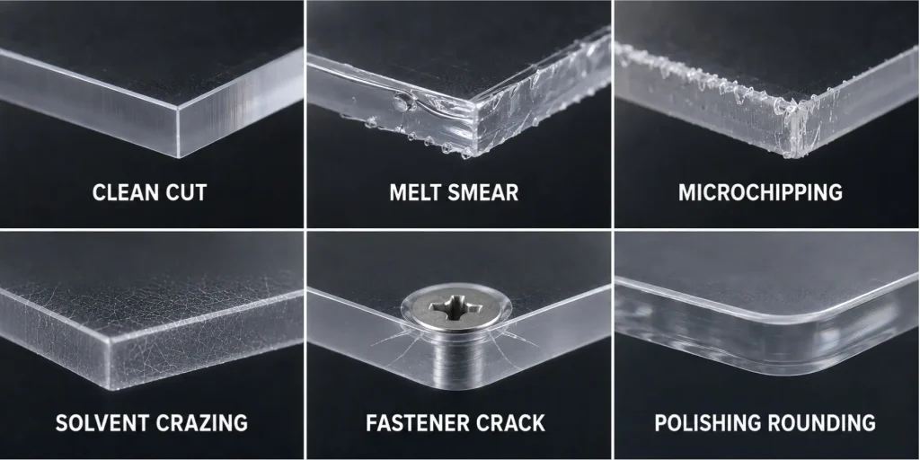
These signs are diagnostic clues, not proof of one cause. Change one controlled variable at a time and compare the location and pattern of the defect. A problem limited to the pocket floor, exit corner, or one clamped edge may indicate a local mechanism rather than an incorrect speed for the complete part.
Air, vacuum extraction, or a compatible cutting fluid may help with chip and heat control for suitable setups. Any fluid, cleaner, adhesive, or residue that contacts the part should be reviewed for compatibility with the exact acrylic grade and its stress condition.
Design Acrylic Holes and Fastener Seats Against Delayed Crazing
Some acrylic holes fail after machining rather than during the cutting operation.
The bore may meet size, but a chipped exit, sharp countersink edge, stressed thread, small ligament, or excessive fastener load can become the starting point for a later crack. Cleaning chemicals or bonding solvents may reveal residual stress that was not visible at final machining inspection.
Drilled Holes
The drill must cut and clear chips instead of wedging or rubbing. Heat can rise when chips remain in a deep hole, while breakout can occur when the remaining material at the exit loses support. A sacrificial backing surface, suitable drill geometry, controlled breakthrough, and chip-clearing strategy may reduce these risks depending on the hole and setup.
Pecking is useful only when it actually clears chips. Repeated shallow motion with rubbing, long dwell, or poor evacuation may add heat instead of removing it.
Countersinks and Fastener Seats
A generic “deburr all holes” note does not define a functional acrylic countersink. If the fastener head seats on the feature, specify the required angle, diameter or depth, and assembly purpose. Review how tightening force is distributed and whether the design needs clearance, a washer, a compliant interface, an insert, or another load-control method.
Do not treat a polished countersink as automatically safer. Finishing can round the seat, change contact, and introduce heat or stress.
Directly machined threads may be used when the thread is not the primary load-bearing element and the material grade, wall thickness, thread form, engagement, and tightening method have been reviewed. Acrylic threads should not be relied upon to carry substantial clamp load or repeated service without a separately reviewed retention strategy.
For repeated disassembly, a metal insert, through-bolt and nut, or another retention method may be considered. The insert installation method still needs review because press fit, heat, and local expansion can introduce their own stresses.
Simply enlarging a countersink is not a universal fix. A conical fastener head can continue to wedge the acrylic when contact and tightening load are not controlled.
Internal Corners and Thin Ligaments
Sharp internal intersections and thin material between a hole and an outer edge can raise local stress. A usable internal radius, sufficient supporting material, and a toolpath that avoids abrupt engagement may reduce both machining and assembly risk.
The appropriate radius and edge distance depend on part thickness, hole function, fastener load, material grade, and service conditions. A single shop default should not replace the drawing requirement.
Annealing may reduce residual stress for a suitable acrylic grade and process route. It does not repair a crack, restore material removed by chipping, or correct an overloaded fastener design.
Protect Clear Faces Through Workholding and Cutting Sequence
Workholding evidence that would be irrelevant on an internal metal bracket can reject a transparent acrylic cover.
Fixture pressure may create dents, whitening, scratches, or temporary deformation. If a thin sheet is clamped flat and machined in that condition, it may change shape after release. Inspection performed only while the part is constrained can therefore hide a free-state problem.
A suitable fixture may use:
- A clean, flat sacrificial support under sheet stock.
- Distributed clamping away from thin walls and visible surfaces.
- Soft jaws or a fitted nest for a three-dimensional component.
- Vacuum workholding for suitable sheet geometry, with leakage and local support reviewed.
- Sacrificial stock, tabs, or staged removal when the finished perimeter would otherwise lose support.
- Protective interlayers that do not contaminate, emboss, or chemically attack the acrylic.
Protective film can reduce handling scratches when it is compatible with the operation. It can also hide contamination, lift near a cut, interfere with vacuum sealing, or be pulled toward a cutter. The decision to leave it on should be made for the actual stock, fixture, and toolpath.
Clamp location should also be reviewed against the cutting sequence. Removing a large pocket changes local stiffness. A clamp that was safe on solid stock may distort a thin remaining wall later in the cycle.
These controls add cost through fixture design, sacrificial material, setup time, careful cleaning, intermediate inspection, and slower handling. That cost should protect a stated cosmetic, dimensional, assembly, or crack-risk requirement rather than become an unexplained shop precaution.
Choose Edge Finishing Before Bonding or Chemical Exposure
Edge finishing is not a separate cosmetic decision. It can change dimensions, corner shape, residual stress, bonding performance, and later chemical resistance.
| Edge Route | Suitable Starting Point | Main Risk | Drawing and Inspection Note |
|---|---|---|---|
| Controlled as-machined edge | Hidden edges, functional parts, or features where geometry dominates | Visible tool marks, local whitening, or small breakout | Define allowable chips and whether the edge is cosmetic |
| Wet sanding and mechanical buffing | Accessible visible edges requiring gradual refinement | Edge rounding, uneven removal, frictional heat, and trapped compound | Protect critical faces and inspect final size after polishing |
| Machine or diamond edge finishing | Straight or accessible edges needing a consistent clear appearance | Tool access, setup marks, remaining cutter pattern, and added material removal | Define which edges receive the process and the acceptable reference finish |
| Flame polishing | Selected thin or accessible edges where a rapid high-gloss result is appropriate | High local stress, distortion, rounded edges, coating damage, or later crazing | Review grade, geometry, annealing, bonding, chemical exposure, and post-finish inspection |
Flame polishing deserves particular caution. The glossy result can hide the fact that rapid surface heating introduced stress. A flame-polished edge may also be unsuitable for later solvent bonding, and some coated acrylic products prohibit the operation.
If flame polishing is proposed, confirm what happens next:
- Will the edge be bonded or printed?
- Will it contact cleaners, solvents, paint, threadlocker, or adhesive fumes?
- Is the edge close to a hole, notch, thin wall, or tight dimension?
- Does the material manufacturer require or recommend annealing?
- Can the part tolerate the thermal cycle and possible dimensional change?
Annealing should not be treated as automatic approval for later solvent bonding or chemical exposure. Compatibility still needs to be checked for the exact acrylic grade, stress condition, joining process, and contact material.
Mechanical polishing is not risk-free. Excessive pressure or time can generate heat, round a sharp profile, and create waves. A highly reflective edge may still distort an image or fail a defined optical requirement.
The drawing should identify the edges to finish and the acceptance result. “Polish all edges” is incomplete when some edges are datums, bonding surfaces, fastener seats, or dimensionally critical features.
Inspect Acrylic After Fixture Release and Under Defined Lighting
Dimensional equipment does not determine whether a transparent part looks acceptable, and visual inspection does not prove that a hole pattern or flat mounting face is within tolerance.
Dimensional Inspection
Measure critical features in the required final condition. That may mean after unclamping, after edge finishing, after an agreed stabilization period, at a controlled inspection temperature when relevant, or in a defined restrained state when the assembly function requires it.
Measurement force matters on thin walls and flexible sheet. Contact tools can deflect the feature or mark a visible face. Vision equipment, non-marring fixtures, gauges, micrometers, or a CMM may be appropriate depending on the geometry and tolerance.
Use the CNC machining tolerances guide to separate functional dimensions from unnecessarily tight general limits. When datum-related geometry or complex feature relationships require coordinate measurement, the CMM inspection guide for CNC machined parts explains why alignment, restraint, probe access, and report scope still matter.
A CMM does not measure haze, clarity, scratches, or acceptable cosmetic appearance merely because it produces a dimensional PASS result.
Cosmetic Inspection
Define the visual inspection condition before production. Useful controls may include:
- Which faces and edges are visible after assembly.
- Whether inspection occurs in reflected light, transmitted light, or both.
- Lighting direction, background, viewing distance, and viewing time when controlled.
- Whether magnification is permitted or required.
- Allowable scratches, chips, white marks, bubbles, inclusions, tool lines, haze, or polishing waves.
- Different acceptance zones for primary, secondary, and hidden surfaces.
- An approved reference sample when written limits cannot communicate the complete appearance.
- Whether protective film is removed before inspection and who may remove it.
Optical and Functional Inspection
If the part guides light, protects a sensor, sits in a viewing path, or forms part of an optical assembly, state the performance requirement and test method. “Optically clear” without a measurable definition can create disagreement even when both supplier and buyer acted reasonably.
Fastener and chemical exposure may also belong in the acceptance plan. When delayed crazing is a functional risk, an agreed assembly or compatibility evaluation may provide more useful evidence than inspecting the freshly polished part under ordinary room light.
Put Visibility Zones, Final Dimensions, and Chemical Contact on the RFQ
The quotation should be based on the finished acceptance condition, not only a STEP model and the word “PMMA.”
| Drawing or RFQ Item | What to Define | Error It Prevents |
|---|---|---|
| Acrylic specification | Exact grade, manufacturer when controlled, cast/extruded/coated condition, color, and permitted equivalent | Substitution between materials with different processing restrictions |
| Stock-surface use | Whether original sheet faces remain and whether nominal stock thickness is functional | Treating raw sheet thickness as a controlled machined dimension |
| Visible zones | Primary faces, secondary faces, hidden faces, and visible edges | Applying one undefined cosmetic standard to the complete part |
| Edge result | As-machined, sanded, buffed, machine-polished, flame-polished, or approved reference | Supplier and buyer expecting different levels of clarity |
| Crack-sensitive features | Hole purpose, countersink, thread, fastener, load, thin ligament, and internal radius | Passing size inspection while leaving a later crack path |
| Post-machining exposure | Bonding, cleaners, paint, printing, adhesive, threadlocker, or other chemical contact | Residual stress appearing as delayed crazing |
| Final dimensions | Critical dimensions after finishing, free-state or restrained condition, and datum scheme | Measuring the wrong process stage or constraint condition |
| Appearance inspection | Lighting, background, viewing distance, defect limits, zones, and reference sample | Subjective acceptance disputes |
| Optical requirement | Transmission, haze, distortion, coating, or project-specific test when applicable | Treating surface gloss as optical performance |
| Protection and packaging | Protective film, interleaf, individual wrapping, contact restrictions, and removal responsibility | Scratches or chemical marks after final inspection |
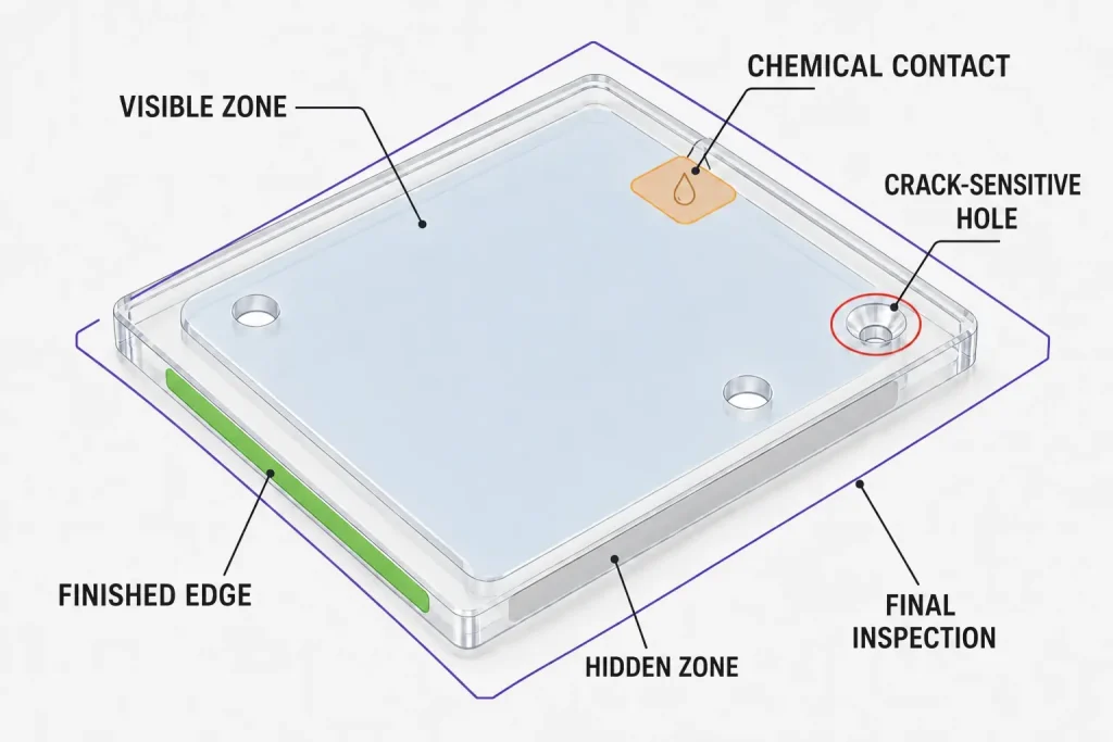
Cost may rise when the part needs specialty stock, a protected fixture, multiple finishing stages, stress-relief treatment, controlled visual inspection, optical testing, first-off approval, or individual packaging. These are separate operations, and each should protect a stated requirement.
Before quotation, provide:
- The STEP model and controlled 2D drawing.
- Exact PMMA grade and stock condition.
- Color, transparency, coating, and original-surface requirements.
- Visible faces and edges.
- Required edge-finishing route or appearance reference.
- Hole, countersink, thread, fastener, and assembly-load information.
- Bonding, cleaning, printing, painting, and chemical exposure.
- Critical dimensions and the required inspection state.
- Cosmetic or optical acceptance method.
- Protective-film, cleaning, and packaging requirements.
- Quantity and any first-off approval requirement.
Rapid Efficient can review the acrylic specification, geometry, workholding risk, edge-finishing route, dimensional and appearance inspection, handling, and packaging requirements before quotation. For suitable custom PMMA parts, submit the complete information through our CNC machining services page so the manufacturing and acceptance routes can be reviewed together.