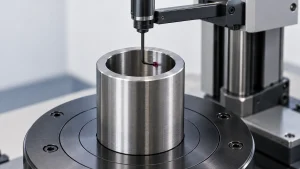
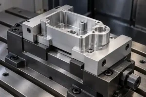
Alodine vs anodize becomes easier to evaluate when the decision starts with the surface that must remain functional after finishing.
A grounding pad, a sliding rail, a cosmetic enclosure, and a precision bearing bore may all be machined from the same aluminum alloy, but they should not automatically receive the same finish.
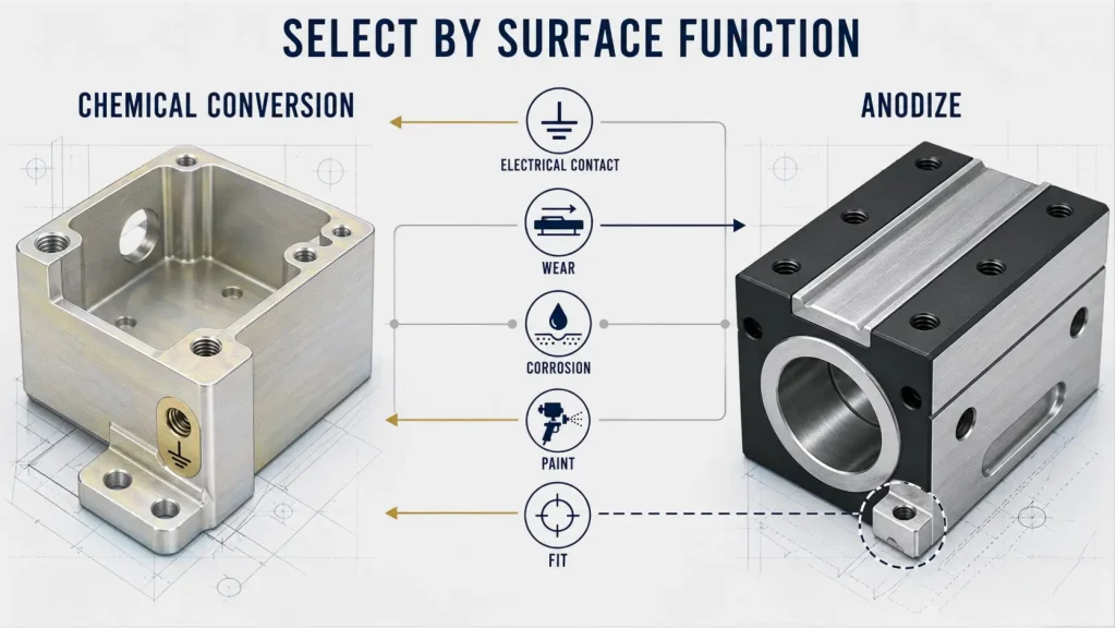
Alodine, commonly used as a trade name for chemical conversion coating, is usually selected when electrical contact, paint adhesion, low dimensional change, or corrosion protection without a thick wear-resistant oxide layer matters.
Anodize creates a more substantial aluminum oxide layer. It is normally selected when the surface needs wear resistance, greater durability, decorative color, or electrical insulation.
Use a properly specified chemical conversion coating for conductive contact areas, paint preparation, and minimal dimensional change. Use Type II or Type III anodize for appearance, wear, and surface durability. If one part needs both functions, divide it into controlled finish zones instead of forcing one process onto every surface.
The finish name alone is not a complete drawing requirement. The engineering decision must also define the governing specification, Type, Class, thickness where applicable, masking boundaries, final dimensional condition, and inspection evidence.
Start With the Surface That Must Still Work
Instead of asking which finish is generally “better,” identify what each surface must do after machining, finishing, storage, and assembly.
| Surface requirement | Preferred starting point | What still needs to be defined |
|---|---|---|
| Carry a grounding or EMI contact | MIL-DTL-5541 Class 3 chemical conversion coating | Type, contact area, mating finish, pressure or torque, resistance test |
| Receive primer or paint | Often MIL-DTL-5541 Class 1A | Type, paint system, cleaning, adhesion requirement |
| Retain a close fit with minimal coating buildup | Chemical conversion coating or a masked anodize zone | Final dimension, masking boundary, pretreatment allowance |
| Provide decorative color and general surface durability | MIL-PRF-8625 Type II | Class, dye, thickness, sealing, appearance standard |
| Resist repeated abrasion or sliding wear | MIL-PRF-8625 Type III | Thickness, sealing, counterface, lubricant, final fit |
| Combine a durable body with a conductive pad | Dual-finish zoning | Process sequence, masking line, rack point, local inspection |
This decision map does not make one finish universally superior. It connects each finish to the surface function that must survive production and assembly. For other available treatments, see our surface finishes for CNC-machined parts.
The finish name comes after the surface function, not before it.
A Grounding Pad Changes the Answer
“Alodine” is a legacy Henkel trade name that is still widely used in engineering and purchasing language. The generic process is an aluminum chemical conversion coating, also commonly called chem film or chromate conversion coating.
It is not a thin version of anodizing. Chemical conversion treatment reacts with the aluminum surface and forms a relatively thin protective conversion layer without intentionally producing the thick aluminum oxide structure associated with anodizing.
A drawing that states only Alodine leaves several decisions unresolved:
- Which specification controls the process?
- Is hexavalent chromium permitted?
- Is the surface intended for painting?
- Is low electrical contact resistance required?
- Is Class 1A or Class 3 appropriate?
- Is a qualified material or approved supplier required?
- Must the delivered part pass an electrical test?
Under MIL-DTL-5541, both Type and Class must be considered.
| Designation | Controlled meaning |
|---|---|
| Type I | The composition contains hexavalent chromium |
| Type II | The composition contains no hexavalent chromium |
| Class 1A | Maximum corrosion protection, painted or unpainted |
| Class 3 | Corrosion protection where low electrical resistance is required |
Type and Class answer different questions. A drawing can therefore specify MIL-DTL-5541 Type II, Class 3 when it needs a non-hexavalent system and a low-resistance electrical interface.
Class 3 Does Not Guarantee the Complete Grounding Joint
Class 3 is not bare aluminum, and it does not mean zero resistance.
MIL-DTL-5541 notes that Class 3 materials qualified under MIL-DTL-81706 must not exceed a contact resistance of 5,000 microhms per square inch as supplied or 10,000 microhms per square inch after 168 hours of salt-spray exposure, when measured under a nominal electrode pressure of 200 psi.
These are controlled material-qualification conditions. They are not an automatic product-level acceptance test for every delivered CNC part. Whether production parts require electrical contact-resistance testing must be stated in the contract or purchase order.
The assembled result can also change with:
- Contact pressure
- Fastener preload
- Surface roughness
- Electrode or mating-area flatness
- Contamination
- Corrosion products
- Storage environment
- Mating-material finish
- Fretting or vibration
- Galvanic compatibility
For a critical grounding joint, specify the contact zone, hardware, mating finish, fastener torque or contact pressure, environmental exposure, and assembled resistance test.
Do not replace these requirements with a generic washer callout. A toothed washer may penetrate a surface film, but it can also damage the finish, expose base metal, or create debris. A Belleville washer can help maintain preload, but it does not independently prove electrical continuity.
A Wear Surface Changes the Answer Again
Anodizing uses an electrolytic process to convert the aluminum surface into aluminum oxide. Part of the resulting structure penetrates the original aluminum surface, while the remainder grows outward.
For CNC-machined components, the most relevant MIL-PRF-8625 designations are:
| Designation | Controlled meaning |
|---|---|
| Type II | Conventional sulfuric-acid anodizing |
| Type III | Hard anodizing for greater abrasion and wear resistance |
| Class 1 | Non-dyed |
| Class 2 | Dyed |
The anodize Class numbers must not be confused with the chemical-conversion classes.
Under MIL-PRF-8625, Class 1 and Class 2 describe whether the anodic coating is dyed. Under MIL-DTL-5541, Class 1A and Class 3 describe the required conversion-coating function.
Type II anodize is commonly used for general corrosion protection, appearance, and moderate surface durability. Type III creates a thicker and harder functional oxide, but it also produces greater dimensional change and requires more attention around threads, fits, sharp edges, thin walls, and fatigue-sensitive geometry.
Hard anodize is not automatically black. A Type III Class 1 finish may appear gray, bronze, brown, or another alloy-dependent shade. Black requires a dye or coloring requirement and does not prove the coating’s hardness.
Sealing also needs to be controlled. It can improve corrosion resistance and retain dye, but it may affect abrasion behavior. The drawing should state the required condition instead of relying on a shop default.
If the actual decision is between an anodic coating and a thicker decorative coating, see our anodizing vs powder coating guide.
A Coating Measured in Microns Can Still Close a Fit
A thin-looking coating can still cause a bearing bore, press fit, threaded feature, or locating diameter to fail assembly.
Two common drawing mistakes are:
- Adding the entire anodize thickness as outward buildup
- Applying a universal 50/50 penetration-and-growth rule to every anodizing process
For a cylindrical diameter anodized uniformly on both opposing surfaces, let:
- t = total anodic coating thickness
- f = approximate fraction that grows outward
The approximate finished dimensions are: ODfinal≈ODbefore+2ft IDfinal≈IDbefore−2ft
Under nominal Type II conditions, a commonly used engineering estimate is approximately two-thirds penetration and one-third outward growth: f≈31
Under nominal Type III hard-anodize conditions, the common approximation is approximately one-half penetration and one-half outward growth: f≈21
These ratios are consistent with the dimensional guidance published by the Aluminum Anodizers Council.
Worked DFM Examples
| Finish | Total coating thickness | Approximate outward growth per surface | Approximate OD increase | Approximate bore reduction |
|---|---|---|---|---|
| Type II | 15 µm | 5 µm | 10 µm | 10 µm |
| Type III | 50 µm | 25 µm | 50 µm | 50 µm |
These are process-planning estimates, not universal acceptance values.
Alloy, electrolyte, temperature, current density, geometry, local current distribution, cleaning, etching, and the finishing supplier’s process can alter the final result. Pretreatment etching may also remove additional base material before the anodic coating forms.
The equations should not be applied unchanged to:
- A single coated face
- A partially masked diameter
- An interrupted cylindrical surface
- A tapered feature
- A deep blind bore with uncertain coating distribution
- A complex profile with nonuniform current density
Bores and Threads Need a Stated Final Condition
The drawing should answer:
- Does the dimension apply before or after finishing?
- Is anodize allowed throughout the complete bore?
- Must the bore be masked?
- Has the coating-thickness range been included in the fit calculation?
- Are threads anodized, plugged, masked, oversized, or machined afterward?
- If material is removed afterward, how is the exposed aluminum protected?
- Is acceptance based on a finished-size measurement or a pre-finish dimension?
- Which datum controls final inspection?
Post-anodize reaming or tapping may recover a dimension, but it removes the anodic protection from the machined area. That route must be an intentional engineering decision, not an unplanned correction by the supplier.
For the wider relationship between process capability, coating allowance, and final inspection, see our CNC machining tolerances guide.
The Most Difficult Parts Need Two Finish Zones
A single aluminum component can require anodize on the main body and chemical conversion coating on selected contact areas.
Typical examples include:
- An anodized electronics enclosure with Class 3 grounding pads
- A black-anodized housing with conductive connector faces
- A hard-anodized sliding component with separately controlled mounting interfaces
- An anodized bracket with local bonding or EMI contact zones
- A part with a wear-resistant exterior and a precision masked bore
The engineering challenge is not simply whether two finishes are possible. It is controlling the boundary and process sequence.
The Masking Line Has Physical Width
A masking boundary is not a mathematically perfect zero-width line. Depending on geometry and process control, the transition may include slight overlap, recession, feathering, or edge variation.
The drawing should identify:
- The exact surface or zone to be masked
- The datum used to locate the boundary
- The permitted boundary-position tolerance
- Whether slight overlap or recession is acceptable
- Whether the transition may occur on an edge, chamfer, radius, or flat face
- Whether the masked area receives another finish
- Where rack-contact marks are permitted
- Which surfaces carry cosmetic requirements
A note such as MASK CRITICAL AREAS does not identify the actual controlled geometry.
The Rack Point Must Be Planned
Anodizing requires a reliable electrical rack connection. The finisher must determine where that contact is made and whether the area remains bare, is masked, is locally prepared, or receives another treatment later.
A pre-existing conversion-coated contact area may not be an appropriate anodizing rack interface. Poor current transfer can contribute to local heating, arcing, weak coating formation, or visible defects.
However, there is no single mandatory sequence for every dual-finish part.
Depending on the approved process, the supplier may use:
- Dedicated bare rack-contact points
- Planned masking
- Local surface preparation
- Conversion coating applied to selected areas after anodizing
- Controlled stripping or mechanical preparation
- Another design-authorized route
Any post-anodize machining or stripping must be reviewed for dimensional change, edge damage, exposed aluminum, cleanliness, corrosion protection, and loss of wear resistance.
A useful drawing structure might state:
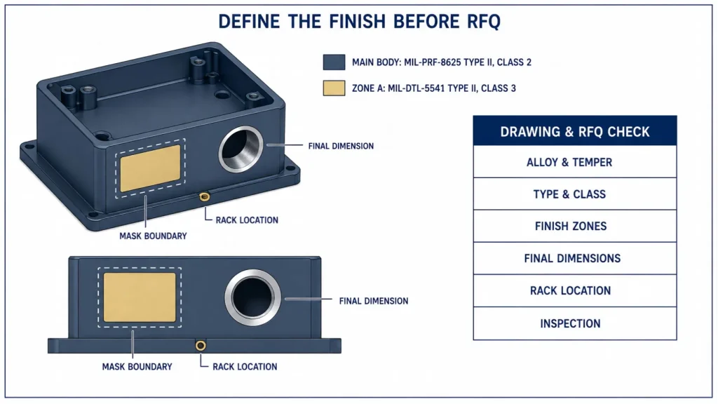
Main surfaces: MIL-PRF-8625 Type II, Class 2, black, specified thickness.
Zone A: No anodize; apply MIL-DTL-5541 Type II, Class 3.
Identified dimensions apply after all finishing.
Masking boundary and permitted rack-contact locations shall be as shown.
This is an example structure, not a universal process instruction. The actual thickness, boundary tolerance, application method, and inspection requirements must be agreed with the finishing supplier and design authority.
Color Is Weak Receiving Evidence
Color can support visual inspection, but it cannot independently prove the chemical system, coating class, or regulatory status.
Traditional hexavalent-chromium products often produce yellow, gold, or iridescent films. Some trivalent-chromium products produce clear, pale-iridescent, or blue-gray surfaces.
For example, Henkel identifies BONDERITE M-CR 1132 AERO as a hexavalent-chromium product that leaves a yellow-gold appearance, while BONDERITE M-CR 871 AERO is a trivalent system that leaves a clear-iridescent appearance.
That is a product-specific example—not a universal color-identification rule.
The correct specification boundary is:
- Type I contains hexavalent chromium.
- Type II contains no hexavalent chromium.
- Type II is not automatically synonymous with TCP.
- A Type II system may use trivalent chromium or another non-hexavalent chemistry.
- Clear appearance does not independently prove Type II.
- Gold appearance does not independently establish the complete specification.
RoHS and REACH are also different regulatory frameworks. Neither should be inferred solely from Type II, TCP, a product color, or an informal statement such as RoHS Alodine.
Compliance should be supported by the applicable supplier declaration, approved material, customer requirement, and current regulatory scope under RoHS Directive 2011/65/EU or the REACH Regulation, as applicable.
Anodize color also varies with:
- Alloy and temper
- Wrought or cast stock
- Surface machining texture
- Bead blasting or polishing
- Coating thickness
- Dye and sealing process
- Part geometry
- Different production lots
If cosmetic matching matters, define an approved reference sample, viewing condition, gloss or texture expectation, and whether mating parts must be processed in the same lot.
Read the Drawing From the Finisher’s Side
Before releasing the drawing, follow the information in the order the machine shop and finishing supplier will need it.
| Release decision | Drawing or RFQ must define | Likely failure if omitted |
|---|---|---|
| Base material | Alloy, temper, wrought or cast stock, welded areas and inserts | Appearance, coating response or compatibility changes |
| Main finish | Governing specification, Type and Class | Supplier selects an unsuitable chemistry or performance level |
| Local finish zones | Grounding pads, wear faces, bores, threads and paint areas | One finish is applied across surfaces with conflicting functions |
| Coating thickness | Nominal or permitted range where applicable | Fit, wear life and appearance remain uncontrolled |
| Sealing and color | Sealed or unsealed condition, dye and approved sample | Abrasion, corrosion or cosmetic expectation changes |
| Dimensional condition | Which dimensions apply after all finishing | Finished part passes pre-finish inspection but fails assembly |
| Masking boundary | Datum, position tolerance and transition allowance | Coating enters a fit or stops short of a protected area |
| Rack-contact location | Permitted functional or non-cosmetic surfaces | Rack marks appear on sealing, visible or mating areas |
| Electrical interface | Contact zone, mating finish, hardware, torque or pressure | “Conductive coating” is present but the joint still fails |
| Inspection | Test method, sampling, coupon use and acceptance limit | Supplier and buyer apply different acceptance methods |
| Documentation | Certificate, process record, declaration or inspection report | Correct processing cannot be objectively demonstrated |
Alloy and surface preparation are part of this review. Copper-rich alloys, high-silicon cast aluminum, welded regions, mixed stock forms, bead-blasted surfaces, and polished surfaces may not produce the same appearance under an otherwise identical finish callout.
Translate Vague Notes Before Release
The following notes are incomplete unless additional requirements are supplied:
ALODINEROHS ALODINECONDUCTIVE FINISHBLACK ANODIZEHARD ANODIZE 50 µmMASK ALL CRITICAL AREASNO RACK MARKSMATCH BLACK COLOR
A controlled drawing replaces these statements with the specification, Type, Class, thickness, exact finish zone, boundary tolerance, final dimensional condition, permitted rack area, and objective inspection evidence.
Three Parts, Three Different Decisions
The following are representative engineering examples, not customer production records.
| Representative part | Functional requirement | Suitable starting decision | Drawing controls that matter |
|---|---|---|---|
| RF electronics enclosure | Durable black body plus conductive connector and grounding pads | Type II Class 2 anodize on the body; Type II Class 3 conversion coating on contact zones | Masking boundary, rack point, mating hardware, final assembled resistance |
| Aluminum sliding guide | Abrasion-resistant running surface with a controlled mounting bore | Type III on the wear zone; calculate or mask the precision bore | Thickness, sealing, counterface, lubricant, final bore size |
| Painted precision bracket | Paint adhesion, corrosion protection and minimal fit change | Class 1A conversion coating under the specified paint system | Alloy, pretreatment, paint system, fit condition and adhesion test if required |
These examples show why aluminum finish should not be treated as a single whole-part choice. The correct decision may exist at the individual-surface level.
Build Inspection Around the Failure Mode
Inspection should verify the reason the finish was selected.
| Possible failure | Appropriate evidence |
|---|---|
| Wrong conversion-coating chemistry | Process certification, approved material and Type declaration |
| Grounding joint has excessive resistance | Defined assembled-joint resistance test |
| Anodized bore closes beyond fit limit | Final dimensional inspection after finishing |
| Coating is too thin or too thick | Controlled thickness measurement on the part or approved coupon |
| Masking boundary moves into a functional area | Boundary inspection from the specified datum |
| Rack mark appears on a critical surface | Visual inspection against permitted rack locations |
| Dyed parts do not match | Approved reference sample and controlled viewing condition |
| Paint does not adhere | Specified adhesion test on the defined paint system |
| Type III wear performance is critical | Applicable abrasion requirement and controlled test evidence |
| Corrosion performance must be demonstrated | Specified corrosion test, sampling plan and acceptance criteria |
A certificate stating only anodized does not prove that a finished bore meets size. A continuity-meter beep does not prove that a grounding joint meets its required resistance after assembly or environmental exposure.
The test location, method, contact pressure, sampling, acceptance limit, and use of production parts or representative coupons should be agreed before the order is released.
Release the Drawing Only When the Function Is Verifiable
Before choosing between Alodine and anodize, close three decisions:
- What must each surface do?
Carry electrical contact, accept paint, resist wear, provide color, retain a fit, or combine several functions. - What finish zone produces that function?
Define the governing specification, Type, Class, thickness, sealing, masking boundary, and permitted rack location. - What evidence proves the finished part works?
Use final dimensional inspection, coating certification, thickness measurement, appearance controls, or assembled electrical testing as required.
A finish name without these decisions transfers engineering responsibility to the supplier and creates avoidable disputes during inspection.
RapidEfficient can review machining allowance, finish zoning, precision bores, masking requirements, and final-condition inspection for custom aluminum parts. Send the drawing, alloy, quantity, mating-part information, and finish requirement through our CNC aluminum machining services page.
Frequently Asked Questions
What is the main difference between Alodine and anodize?
Alodine is commonly used to describe a thin aluminum chemical conversion coating. It is useful for paint preparation, corrosion protection, low dimensional change, and Class 3 electrical contact surfaces. Anodize creates a thicker aluminum oxide layer for wear resistance, durability, appearance, or electrical insulation.
Is Alodine electrically conductive?
MIL-DTL-5541 Class 3 is intended for applications requiring low electrical contact resistance. However, the coating does not guarantee the resistance of the complete assembled joint. Contact pressure, hardware, contamination, mating finish, and environmental exposure must also be controlled.
Can anodized aluminum be used as a grounding surface?
Anodic aluminum oxide is normally electrically insulating. A grounding area is usually masked, locally conversion coated, or otherwise prepared under a controlled requirement. Critical grounding performance should be verified on the assembled joint.
Does anodizing change part dimensions?
Yes. Part of the anodic coating penetrates the original aluminum and part grows outward. Under nominal conditions, Type II is often estimated at approximately one-third outward growth, while Type III is often estimated at approximately one-half. Critical fits should use the finishing supplier’s actual process range.
Can one aluminum part have both finishes?
Yes. A part can be anodized on the main body and receive Class 3 conversion coating on grounding pads or connector faces. The drawing must define the finish zones, masking boundary, rack location, process approval, final dimensions, and inspection requirements.
Does MIL-DTL-5541 Type II always mean TCP?
No. Type II means the conversion coating contains no hexavalent chromium. The approved system may use trivalent chromium or another non-hexavalent chemistry.
Is gold-colored conversion coating always Type I?
No. Color alone cannot prove the specification, chemistry, Type, or Class. Acceptance should be based on the controlled process and supporting documentation.
Should Type III hard anodize always be sealed?
No universal answer applies. Sealing can improve corrosion performance, but it may affect abrasion behavior. The required condition should follow the functional requirement and be stated on the drawing or purchase order.