A shaft can meet its diameter limits at several measured sections and still bow enough to interfere with an assembly. A machined rail can look straight along one edge but deviate along another line. Both problems may be described as straightness, but they do not necessarily represent the same GD&T control.
The straightness symbol alone does not identify what must be inspected. Its attachment determines whether the drawing controls a surface line element or the derived median line of a feature of size. That decision changes the tolerance-zone shape, the interaction with size limits, the use of material-condition modifiers, and the appropriate inspection method.
For CNC-machined parts, support position, gravity, clamping, machining stress, temperature, sampling, and software evaluation can also change the reported result. A useful straightness requirement must therefore define the controlled geometry and the condition in which it will be accepted.
Quick Answer: What Does Straightness GD&T Control?
Straightness GD&T is a datum-free form control. Its symbol is a single straight line.
When applied directly to a surface, it controls each applicable line element between two parallel straight lines separated by the stated tolerance.
When applied to a cylindrical feature of size, it can control the feature’s derived median line inside a cylindrical tolerance zone. On applicable ASME drawings, this feature-of-size control may use MMC or LMC.
The attachment of the feature control frame—and the presence or absence of a diameter symbol—determines which geometry is controlled.
Straightness does not by itself control location, orientation to another feature, roundness, or rotational runout.
The Drawing Must Choose Which Line Is Controlled
“Surface straightness” and “axis straightness” are convenient shop terms, but they describe different controlled objects. In a cylindrical feature-of-size requirement, the more precise term is straightness of the derived median line.
| Drawing decision | Surface line-element straightness | Derived median-line straightness |
|---|---|---|
| Controlled object | A line element on the actual surface | The derived median line of a shaft, bore, or applicable feature of size |
| Typical callout attachment | Leader or extension line associated with the controlled surface | Associated with the feature’s size dimension according to the governing drawing rules |
| Tolerance-zone shape | Two parallel straight lines in the applicable cutting plane | A cylindrical zone when the diameter symbol is used |
| Diameter symbol in the tolerance | No | Yes for a cylindrical zone |
| Datum reference | None | None |
| MMC or LMC modifier | Not applicable to the surface control | May be used on an applicable ASME feature-of-size callout |
| Typical functional concern | Guide-line form, sealing contact, sliding contact, or visible edge form | Assembly boundary, shaft bow, bore-center variation, or feature-axis fit |
| Common inspection mistake | Measuring the complete surface as flatness | Treating a rotating indicator reading as a direct derived-line result |
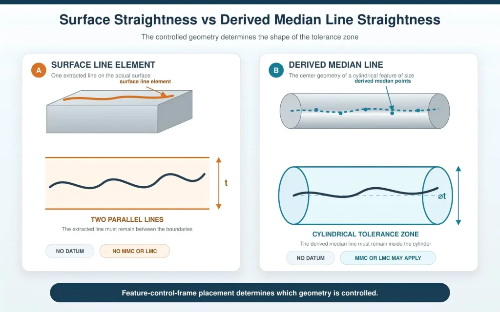
The placement of the feature control frame is therefore not cosmetic. A callout attached directly to a cylindrical surface does not automatically control the shaft’s derived median line. Likewise, a feature-of-size straightness callout does not directly report every local high point on the surface.
A designer should identify the functional failure first. If the problem is a local surface line that must remain straight, use a surface control. If the problem is the center path of a shaft or bore, review a derived median-line control.
Straightness Does Not Establish a Datum Relationship
Straightness controls form without orienting or locating the feature relative to another datum.
A shaft’s derived median line may be straight but tilted relative to a mounting face. A guide surface may have straight line elements but still not be parallel to its base. A bore may be straight but located incorrectly in a housing.
When the functional requirement involves another feature, a different control may be necessary:
- Use perpendicularity GD&T when a surface or axis must be oriented at 90 degrees to a datum.
- Use parallelism when a surface or derived feature must maintain orientation relative to a datum.
- Use position when the location and orientation of a feature of size must be controlled through a datum reference frame.
- Use runout when rotating surface variation relative to a datum axis is functionally important.
Adding a datum reference to a straightness feature control frame does not convert straightness into an orientation control. If a drawing appears to do this, the requirement should be clarified before quotation.
Size, Rule #1, and Material Condition Change the Boundary
A size tolerance and a straightness tolerance answer different questions.
Size controls the allowable dimensions of a feature. Straightness controls the form of a surface line or the path of a derived median line. A diameter inspection by itself does not normally provide a complete numerical straightness result.
For broader decisions about dimensional and geometric requirements, review the CNC machining tolerances guide.
Surface Straightness and Rule #1
A surface straightness callout has no MMC or LMC modifier and creates no bonus tolerance.
Each applicable surface line element must lie between two parallel straight lines separated by the stated tolerance in the applicable cutting plane.
On an ASME drawing, however, that surface may also be subject to Rule #1 when it belongs to a regular feature of size. The surface must satisfy both:
- The explicit surface line-element straightness tolerance
- The applicable size-and-form boundary established by Rule #1
The surface straightness callout does not override Rule #1. At or near MMC, the size envelope may therefore restrict the available surface-form variation more tightly than the explicit straightness value alone suggests.
Derived Median-Line Straightness at RFS
Applying straightness to a feature of size is different from applying it directly to the surface.
Under ASME Y14.5, feature-of-size straightness is an exception to Rule #1. It controls the derived median line through the feature control frame rather than applying the surface-line rule.
When no material-condition modifier is shown, regardless of feature size is normally the ASME default. The stated cylindrical straightness tolerance does not increase as the feature departs from MMC, although the feature must still meet its applicable size limits and collective boundary requirements.
Derived Median-Line Straightness at MMC
For an applicable feature-of-size control at maximum material condition, the stated straightness tolerance applies when the feature is at MMC. Permissible departure from MMC may provide bonus tolerance.
For an external feature such as a shaft:
External virtual condition = MMC size + stated straightness tolerance
For an internal feature such as a bore:
Internal virtual condition = MMC size − stated straightness tolerance
This virtual condition defines a fixed worst-case boundary created by the combined size and straightness requirements. The feature’s local sizes must still remain within their specified limits.
The calculation must follow the governing drawing standard and the actual feature control frame. MMC should not be added merely to make a tolerance easier to manufacture.
Derived Median-Line Straightness at LMC
LMC or the corresponding ISO least-material requirement can establish a least-material boundary for an applicable feature of size.
However, datum-free straightness alone does not locate that feature relative to surrounding geometry. If minimum wall thickness or edge distance depends on another feature, an appropriate location, orientation, or profile control may also be required.
ASME and ISO Defaults Must Not Be Mixed
The drawing should identify the governing GD&T standard and revision.
ASME drawings commonly apply Rule #1 to regular features of size unless an applicable exception is specified. ISO GPS drawings commonly apply the independence principle unless an envelope, maximum-material, least-material, or another defined requirement is indicated.
A supplier should not silently import the default assumptions or terminology of one system into a drawing governed by the other.
Support, Gravity, and Clamping Can Create a False Bend
A straightness report can reflect the part, the support system, or both.
Long and slender shafts may sag when inspected horizontally. Changing the distance between supports changes the deflected shape. Thin tubes may become lobed in a chuck and recover after release. Parts measured between centers can also include center-hole condition and setup alignment in the observed indicator movement.
Standard support-point concepts may be useful for uniform beam-like length standards, but they are not universal formulas for every CNC shaft. The appropriate support arrangement depends on geometry, mass distribution, material, functional orientation, and the inspection requirement.
Straightness Disagreement Diagnostic Map
| Conflicting result | Hidden variable | What the reading may include | Confirmation action |
|---|---|---|---|
| Horizontal inspection fails; vertical inspection passes | Gravity direction | Part form plus transverse sag | Define the functional orientation and repeat with documented support |
| V-block roll check fails; CMM derived line passes | Roundness, eccentricity, V-block angle, or surface variation | Composite radial movement rather than only median-line straightness | Compare roundness, surface runout, and derived-line results separately |
| Clamped measurement passes; released part fails | Fixture restraint or elastic recovery | Geometry forced into the fixture condition | Inspect in the specified free or restrained state |
| Between-centers result differs from supported inspection | Center-hole condition or center alignment | Part form plus center-generated rotation error | Inspect the center holes and reproduce the agreed setup |
| One surface trace passes; another trace fails | Different surface line elements | Local generator-line form | Measure the required lines and angular positions |
| Two CMM reports disagree near the limit | Sampling, filtering, feature construction, or evaluation algorithm | Different mathematical representations of sampled geometry | Reevaluate agreed data under the same standard and settings |
| Pre-finish inspection passes; final inspection fails | Heat treatment, coating, grinding, or stress release | Geometry from different physical process states | Measure the two process states separately under matched support, temperature, sampling, and evaluation settings |
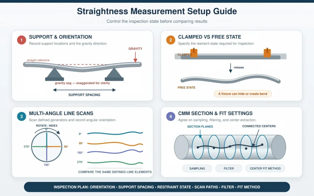
First determine whether the physical part state changed. Then isolate differences caused by support, restraint, setup, sampling, filtering, and data reduction.
The inspection record should identify support locations, orientation, restraint, temperature condition, and the manufacturing stage at which the result was obtained.
For a long part, writing only “inspect straightness” leaves too much undefined. The buyer and supplier should agree whether the functional condition is horizontal, vertical, freely supported, restrained during assembly, or evaluated by a functional boundary.
For a nonrigid part, the drawing or inspection plan should use the applicable free-state indication or clearly define the required restraint when the difference is functionally important.
Inspection Must Match the Controlled Object
The appropriate measuring method depends on whether the drawing controls a surface line or a derived median line.
Inspecting a Surface Line Element
A surface line-element inspection should evaluate the required line direction and location rather than automatically fitting the complete surface as a plane.
Depending on the feature and tolerance, the method may use:
- An indicator and suitable reference setup
- A precision straightedge or comparator method
- A surface-texture or form instrument
- An optical system
- A CMM or scanning system with an appropriate line strategy
Because straightness is datum-free, a raw indicator range relative to a surface plate may include the overall slope of the measured line. The evaluation must establish the applicable floating straightness zone rather than treat the inspection table as an unintended datum.
The specification applies to all applicable line elements. A practical inspection plan can sample selected lines, but the resulting report provides direct evidence only for the lines actually measured. Sampling locations should therefore represent the functional surface and the expected machining variation.
The part should be stable without being distorted by the fixture. If several line elements are sampled, their locations and directions should be distributed over the relevant surface.
Probe-tip diameter, contact force, sampling density, scanning speed, and software filtering can all influence the extracted line. These settings should be appropriate for the surface and kept consistent between supplier and customer. No filter or probe size should be selected merely to obtain a passing result.
Surface roughness parameters such as Ra and Rz do not simply add to straightness as fixed numerical values. However, short-wavelength surface features and probe interaction may influence the extracted profile when the measurement operator is not defined consistently.
Inspecting a Derived Median Line
A derived median-line inspection normally requires measurements at multiple cross-sections along the feature.
The derived median line is an abstract line through the center points of the feature’s cross-sections under the governing definition. A CMM measures a finite set of points and sections, so the reported line is a measured representation rather than a direct observation of every possible cross-section.
The inspection system uses the sampled section data to construct representative centers or median points. The resulting line is then evaluated against the specified cylindrical tolerance zone.
The report should define, when material to the decision:
- Section locations
- Number of sections
- Points or scan density per section
- Probe configuration
- Filtering
- Section-feature construction method
- Straightness evaluation criterion
- Part orientation and support
- Temperature or stabilization condition
- Material-condition modifier and applicable bonus tolerance
Fitted section-circle centers are not automatically equivalent to the required derived median points under every standard or specification operator.
Least-squares feature construction and minimum-zone tolerance evaluation are not interchangeable. A software default that produces a useful fitted axis does not automatically represent the conformance result required by every drawing.
When a result is near the tolerance limit, both parties should use the governing standard and the same agreed construction, filtering, sampling, and evaluation settings. The CMM inspection guide for CNC-machined parts explains how point density, fitting, filtering, restraint, and reporting scope can affect CMM evidence.
What a Roll Check Can and Cannot Prove
Rolling a shaft on V-blocks while reading an indicator is useful for process screening. It can reveal obvious bow, eccentricity, lobing, or surface variation.
It does not isolate derived median-line straightness automatically. The result may combine:
- Shaft roundness
- Surface waviness
- Diameter variation
- Eccentricity
- V-block geometry
- Support spacing
- Gravity sag
- Indicator position
- Center or journal relationships
A functional gauge may be suitable for verifying a combined maximum-material boundary. However, a boundary gauge does not necessarily provide a separate numerical straightness value at RFS.
Straightness Is Not Flatness, Roundness, Cylindricity, or Runout
These controls may describe the same physical part, but they evaluate different geometric characteristics.
| Control | Controlled geometry | Tolerance-zone form | Datum required? | Important distinction |
|---|---|---|---|---|
| Straightness of a surface line | One-dimensional surface line elements | Two parallel straight lines | No | Does not control the complete surface as a plane |
| Straightness of a derived median line | Center path of a feature of size | Cylindrical zone when the diameter symbol is used | No | Does not locate or orient the feature to another datum |
| Flatness | Complete surface | Two parallel planes | No | Controls the surface in two dimensions rather than individual lines only |
| Roundness | Each circular cross-section | Two concentric circles | No | Does not control the full axial surface |
| Cylindricity | Complete cylindrical surface | Two coaxial cylinders | No | Controls the complete cylindrical form without a datum |
| Runout | Surface variation during rotation relative to a datum axis | A datum-related zone generated about the datum axis; its form depends on whether circular or total runout is specified | Yes | Evaluates datum-related rotational surface behavior rather than isolated straightness |
For long surfaces, the distinction between overall form and local control is discussed further in the guide to flatness tolerance per unit length.
For rotating features, review the concentricity and runout guide before converting an indicator TIR requirement into a straightness callout.
A TIR value should not be transferred one-for-one into a straightness tolerance. Runout may include roundness, eccentricity, angular error, surface variation, datum-axis error, and setup effects.
CNC Machining Can Change Straightness After Release
Straightness is not created only by the final cutting pass. It can change as material is removed, heat is introduced, restraints are released, or secondary operations are completed.
| Machining influence | Typical risk | Review point |
|---|---|---|
| Initial stock condition | Bar, plate, or extrusion already contains bow or residual stress | Inspect or qualify stock where final straightness is critical |
| Asymmetric material removal | Uneven stress release bends the component | Review roughing balance and intermediate release |
| High chuck or collet pressure | Thin cylindrical parts distort during cutting | Use suitable jaws, contact length, and controlled pressure |
| Tailstock or steady-rest force | Support pushes a shaft away from its relaxed shape | Align and control support according to the operation |
| Cutting heat | Temporary thermal curvature changes the measured condition | Stabilize before final acceptance when necessary |
| Tool force on a slender feature | Elastic deflection creates taper or bowed geometry | Review tool engagement, support, and finishing sequence |
| Keyways, flats, slots, or cross-holes | Local asymmetric removal releases stress | Consider feature order and intermediate inspection |
| Heat treatment or straightening | Geometry changes after machining | Define whether final inspection occurs after treatment |
| Grinding or surface finishing | Local heat or material removal changes final form | Reserve suitable process allowance and reinspect |
| Packaging and transport | Unsupported long parts may be bent or damaged | Define protective support where shipping risk is material |
A machining strategy may include staged roughing, part relaxation, balanced stock removal, controlled support, finish machining after stabilization, or final grinding. The appropriate route depends on the material, geometry, tolerance, quantity, and final functional state.
No single operation can guarantee straightness for every long or thin component.
What the Drawing and RFQ Must Define
Writing only “straightness 0.05” does not provide enough information for a reliable quotation or inspection plan.
| Requirement | What to state | Why it matters |
|---|---|---|
| Governing standard | GD&T standard and revision | Prevents ASME and ISO defaults from being mixed |
| Controlled object | Surface line element or derived median line | Determines what geometry must be evaluated |
| Callout attachment | Correct surface leader or feature-size association | Prevents the wrong control from being inspected |
| Tolerance-zone shape | Linear zone or cylindrical zone with diameter symbol | Defines the acceptance boundary |
| Material requirement | ASME RFS/MMC/LMC or the applicable ISO MMR/LMR requirement | Determines size–geometry interaction and any bonus tolerance |
| Controlled length | Full length, local segment, or specified region | Prevents partial inspection from representing the complete feature |
| Part state | Free, supported, restrained, or assembled | Controls the influence of gravity and elastic deformation |
| Support condition | Orientation, number of supports, and support locations when critical | Improves measurement repeatability |
| Manufacturing stage | After machining, heat treatment, grinding, coating, or final finishing | Identifies the physical state that must pass |
| Datum-related function | Separate orientation, position, profile, or runout requirement if needed | Straightness alone does not establish the relationship |
| Inspection evidence | Indicator check, form scan, CMM report, or functional gauge | Aligns the report with the controlled object |
| Measurement settings | Sampling, filtering, feature construction, and evaluation when critical | Reduces near-limit software disputes |
| Conformity decision rule | How uncertainty is handled near the tolerance limit when required | Prevents inconsistent PASS/FAIL decisions |
| Mating requirement | Bearing, guide, seal, sliding fit, or boundary function | Connects the tolerance to assembly risk |
| Quantity and reporting scope | Prototype, first article, sampling, or agreed production inspection | Defines what the report actually proves |
If the functional concern is assembly through a fixed boundary, provide the mating geometry and material-condition requirement. If the concern is free-state bow, provide the installed orientation and support condition. If the concern is rotating performance, define the datum axis and consider whether runout is the correct control.
Five Quick Straightness Answers
Does straightness need a datum?
No. Straightness is a form control and does not establish a relationship to a datum. Use an orientation, location, profile, or runout control when another datum is functionally involved.
Can surface straightness use MMC?
No. MMC and LMC modifiers do not apply to a straightness control placed directly on a surface line element. On an ASME feature of size, however, the surface may still be restricted by the applicable Rule #1 size-and-form boundary.
Does checking several diameters prove axis straightness?
No. Diameter measurements verify local size information. They do not by themselves construct and evaluate the complete derived median line.
Can a shaft pass straightness and still fail runout?
Yes. The shaft’s own derived median line may be sufficiently straight while its rotating surface remains eccentric, out of round, tilted, or misaligned relative to the datum axis.
Why can two CMM reports disagree on straightness?
Different support conditions, section locations, point density, filtering, feature-construction methods, evaluation algorithms, temperature conditions, or restraint states can produce different results. Near-limit reports should be compared under the same agreed measurement procedure.
Review the Straightness Requirement Before Quotation
Rapid Efficient can review straightness-sensitive CNC parts as part of a project-specific drawing and manufacturing assessment.
The review may cover:
- Surface versus derived median-line control
- GD&T standard and Rule #1 interpretation
- Material-condition requirements
- Long-shaft or thin-part support
- Stock condition and machining sequence
- Heat treatment and final finishing state
- CMM, indicator, form-scan, or functional-gauge requirements
- Required inspection reports and sampling scope
Our precision machining services can support suitable shafts, rails, sleeves, bores, guide components, and other parts where form control and inspection planning affect assembly.
For a useful review, provide the 2D drawing, 3D model, governing GD&T standard, controlled feature, tolerance callout, material and condition, overall length and section size, heat treatment or finish, functional orientation, support or restraint requirement, mating geometry, quantity, and expected inspection evidence.
The goal is not simply to assign a smaller straightness value. It is to define the correct controlled line, manufacture the part in a stable state, and verify the same requirement that the assembly actually needs.