Polycarbonate is often selected because it combines transparency with strong impact resistance. That combination can create a dangerous assumption: if the material does not chip like acrylic, the finished part must be safe.
A CNC-machined polycarbonate component can pass dimensional inspection, look clear under ordinary lighting, and still develop whitening, fine crazing, distortion, or cracks after cleaning or assembly.
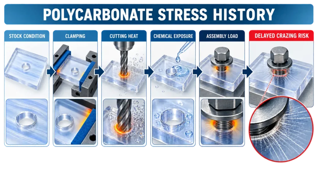
The failure may not come from one bad machining parameter. It may result from several smaller stress sources acting in sequence:
- Residual stress already present in the stock
- Stress introduced while cutting the blank
- Clamping strain stored during machining
- Local heat from rubbing or poor chip evacuation
- Unbalanced material removal
- Heat or chemicals used during polishing and cleaning
- Fastener, insert, adhesive, or assembly load
Quick answer: Polycarbonate is readily machinable, but the machining plan must control its complete stress history. Use sharp tools, remove chips effectively, avoid storing excessive fixture strain, release geometry in stages, confirm chemical compatibility, and inspect the finished part after it has been unclamped, cooled, cleaned, and placed in the agreed acceptance state.
This article primarily addresses unfilled polycarbonate sheet, plate, rod, and tube. Hard-coated, UV-protected, flame-retardant, optical, glass-filled, and other modified grades require grade-specific review.
The Failure Timeline Starts Before the Cutter Touches the Part
“Polycarbonate” is not a complete material specification.
Different PC products may vary in:
- Resin formulation
- Stock-manufacturing method
- Residual stress
- Transparency
- UV protection
- Surface coating
- Flame-retardant performance
- Filler content
- Chemical compatibility
- Annealing history
- Available thickness and flatness
An extruded sheet, a machine-grade rod, a coated glazing sheet, and an optical-grade product should not automatically share one machining route.
The stock itself may already contain frozen-in stress from extrusion, cooling, forming, or previous fabrication. Machining removes material that helped keep those stresses balanced. A flat blank can therefore move after pocketing, facing, drilling, or perimeter release even when cutting forces appear moderate.
Coated and protected sheet introduces another boundary. A hard coat, UV-resistant layer, or original optical face may exist only on a specific side. Facing that surface, breaking through it with a cutter, or polishing it later can remove or interrupt the intended property.
Before programming the part, confirm:
- Exact grade and manufacturer when controlled
- Clear, tinted, opaque, filled, coated, or flame-retardant condition
- Sheet, plate, rod, tube, or molded blank
- Whether original stock faces remain on the part
- Orientation of any one-sided coating or UV-protected surface
- Material traceability requirements
- Whether an equivalent grade is permitted
- Incoming storage and temperature condition
If PC is not yet confirmed as the correct polymer, use the best plastics for CNC machining guide to compare its dimensional, thermal, chemical, and functional limits with other engineering plastics.
Use a Stress Budget Instead of One Speed-and-Feed Rule
A single spindle speed cannot explain every polycarbonate failure.
The more useful model is a stress budget: each manufacturing and service step may add, redistribute, or reveal stress. The finished part fails when the combined condition exceeds what the material, geometry, and environment can tolerate.
Polycarbonate Stress-History Diagnostic Matrix
| Stage | Possible Stress Source | Evidence to Look For | What to Verify Before Changing the Process |
|---|---|---|---|
| Incoming stock | Extrusion, cooling, forming, poor storage, or previous fabrication | Bow, twist, inconsistent behavior between blanks, movement after the first cut | Exact stock grade, lot, thickness, orientation, storage, and supplier condition |
| Blanking | Saw heat, rough cut, unsupported exit, or a damaged edge | Whitening, roughness, edge microcracks, or movement before CNC setup | Saw condition, support, blanking allowance, and whether the damaged edge will be removed |
| Fixturing | Point loading, jaw pressure, vacuum distortion, or clamping a bowed blank flat | Dimension changes after release, clamp marks, localized distortion, or inconsistent free-state flatness | Contact area, clamp location, pressure, support, cleanliness, and free-state behavior |
| Cutting | Dull edge, rubbing, packed flutes, recut chips, excessive engagement, or poor evacuation | Smearing, welded chips, stringy burrs, local haze, heat marks, or changing size while warm | Tool edge, runout, chip thickness, flute capacity, engagement, air flow, and chip exit path |
| Geometry release | Deep pockets, thin windows, asymmetric stock removal, or perimeter cutout | Bow or twist after roughing, unclamping, or tab removal | Roughing sequence, remaining wall stiffness, intermediate release, and finishing allowance |
| Finishing | Buffing heat, sanding pressure, unsuitable compound, or chemical polishing | Glossy surface with rounded edges, local haze, distortion, or delayed crazing | Final dimensions, heat input, compound compatibility, accessible faces, and required appearance |
| Cleaning and assembly | Cleaner, threadlocker, adhesive, lubricant, insert installation, or fastener preload | Crazing around holes, corners, threads, contact pads, or highly loaded edges | Exact chemical, exposure time, temperature, assembly load, washer contact, and representative test condition |
No single symptom proves one root cause. For example, whitening near a hole may come from machining damage, fastener load, chemical exposure, or their combined effect.
The final risk depends on the complete history, not the last operation alone.
Make the Chip Prove That the Tool Is Cutting
Polycarbonate should be cut rather than rubbed.
A sharp cutting edge creates a real chip and carries part of the heat away from the workpiece. A dull tool, very light chip load, packed flute, unstable setup, or repeated chip recutting can turn the cutting zone into a local heater.
Common process evidence includes:
- Clean, consistently formed chips: the edge is more likely cutting effectively
- Smeared or reattached material: local softening or poor evacuation may be occurring
- Dust mixed with irregular fragments: tool condition, engagement, or material condition needs review
- Long chips wrapping around a turning tool: chip control and clearing need improvement
- A burr that stretches instead of breaking cleanly: the tool may be rubbing or the finishing pass may be too light
- Scratches on a transparent face: evacuated chips may be returning across the part
Do not respond to every heat problem by reducing spindle speed. A speed reduction without a corresponding feed and engagement review may reduce chip thickness and create more rubbing.
Likewise, increasing feed is not automatically correct. The usable combination depends on:
- Tool diameter
- Flute count
- Edge geometry
- Tool runout
- Radial and axial engagement
- Feature depth
- Wall stiffness
- Machine rigidity
- Chip evacuation
- Required surface and edge condition
Milling
Milling tools need enough flute space for the chip to leave. Deep pockets and full-width slots deserve extra attention because their walls restrict evacuation and expose the new surface to recut chips.
Air directed at the cutting zone may help remove chips and limit local heat for suitable operations. The air supply must be clean and dry when optical or cosmetic surfaces are involved.
Turning
Polycarbonate rod and tube can generate continuous chips. The plan should prevent chip wrapping, rubbing against the finished diameter, and heating of thin rings or walls.
Jaw pressure also needs review. A bore finished while a tube is compressed may change roundness after the jaws release.
Drilling
Drilling traps both chips and heat inside the feature. A practical route may include:
- A sharp drill suitable for plastic
- Frequent chip clearing where the depth requires it
- Stable support at the entry and exit
- Control of breakthrough load
- Adequate clearance from thin edges
- Inspection for whitening, breakout, burrs, and delayed cracking
The official LEXAN sheet processing guide emphasizes chip clearing, support, heat control, and forced-air cooling for applicable sheet-machining operations. It advises against cutting fluids for the covered LEXAN sheet products. That recommendation should not be converted into a universal rule for every polycarbonate grade or machining route.
If a liquid coolant, cleaner, lubricant, or polishing compound is proposed, its compatibility must be checked against the exact stock product and finished-part exposure.
A Fixture Can Store Trouble in the Part
A fixture may hold a polycarbonate part accurately while also bending it away from its natural shape.
When the cutter machines that restrained geometry, the part may appear correct on the machine. After release, the stored elastic strain becomes dimensional movement.
This is especially important for:
- Large flat covers
- Thin windows
- Deep-pocket housings
- Tubes with thin walls
- Parts with a large perimeter cutout
- Bores finished under jaw pressure
- Features located from a flexible sheet face
- Components with cosmetic clamp-sensitive surfaces
A suitable workholding plan may use broad support, fitted soft jaws, a clean sacrificial plate, a custom nest, vacuum holding, sacrificial tabs, or staged perimeter release. None is automatically correct.
Vacuum workholding can distribute force over a broad area, but it may also pull a thin part against local fixture variation. Soft jaws can protect a surface, but poorly fitted jaws may still create concentrated loads. Protective films or interlayers can reduce scratching but may affect vacuum sealing, thickness, cleanliness, or chemical compatibility.
The fixture review should answer four questions:
- What force keeps the part from moving during the heaviest cut?
- Where does that force enter the polycarbonate?
- Does the force distort a critical wall, bore, datum, or transparent face?
- What changes when the part is released?
A dimension measured only while the part is clamped does not establish its free-state value.
The Highest Risk Features Combine Geometry, Load, and Exposure
A hole is not dangerous simply because it is machined in polycarbonate. Risk rises when several stress concentrators act at the same location.
| Feature Combination | Why Risk Increases | Drawing or Assembly Review |
|---|---|---|
| Hole close to an edge plus tight fastener | Reduced ligament carries concentrated tensile stress | Confirm edge distance, clearance, washer area, and tightening method |
| Countersink plus conical screw head | The head can create a wedging load and hoop stress | Review whether the countersink is functionally required and how clamp load is limited |
| Deep pocket plus sharp internal corner | Material removal reduces stiffness while the corner concentrates stress | Use a functional internal radius and review the roughing sequence |
| Thin window plus perimeter clamping | The window can be machined or inspected in a distorted state | Define support, free-state acceptance, and assembly restraint |
| Direct thread plus repeated tightening | Local thread stress and creep may change retention | Review engagement, torque, service cycles, and whether an insert or through-fastener is more suitable |
| Finished edge plus cleaner exposure | Polishing heat and retained tensile stress may increase sensitivity | Confirm finishing route and evaluate the actual cleaner under representative conditions |
Clearance holes for screws should account for thermal movement and assembly alignment, but they should not be enlarged by an arbitrary shop rule. The required clearance depends on temperature range, part size, fastener layout, constraint direction, sealing requirements, and mating-material expansion.
Impact resistance does not make zero-radius corners, rigidly trapped panels, or uncontrolled countersunk fasteners harmless.
Release the Geometry in Stages
A thin polycarbonate part should not necessarily be taken from solid stock to final size in one fully constrained operation.
For geometries with high material removal or unbalanced walls, a staged route may be more stable:
- Bring the stock and inspection equipment to an agreed working condition.
- Confirm stock orientation, coatings, and protected faces.
- Establish reference surfaces without unnecessarily removing functional stock faces.
- Rough the major pockets or profiles while leaving controlled finishing allowance.
- Remove material from opposing regions in a balanced sequence where geometry permits.
- Release, reposition, or allow the part to stabilize when movement risk justifies the extra stage.
- Finish critical bores, datums, wall thicknesses, and sealing or assembly features in a representative support condition.
- Deburr with a method that limits local heat and edge damage.
- Perform the approved cleaning and finishing operations.
- Inspect the part in its specified final state.
This route costs more than a single clamp-and-finish cycle. It may require additional fixtures, setup time, intermediate measurements, handling protection, and separate inspection.
Those operations should be used to protect identified functional or cosmetic requirements—not added automatically to every PC part.
For dimensions affected by temperature, free-state support, thin walls, and finishing, the CNC machining tolerances guide explains why critical features need a defined tolerance and inspection budget rather than a blanket tight tolerance.
A Clear Surface Can Still Hide a Weak Part
Transparency, appearance, optical performance, and residual stress are different characteristics.
A polycarbonate part may transmit light and still have:
- Cutter marks
- Haze
- Edge whitening
- Surface waviness
- Image distortion
- Residual stress
- Subsurface machining damage
- An interrupted hard coat or UV-protected layer
A glossy edge does not prove that the part is optically accurate. Polishing may improve visible roughness while rounding a corner, changing a finished dimension, heating the edge, or leaving deeper stress unchanged.
The drawing should distinguish among these requirements:
| Drawing Statement | What It May Control | What It Does Not Prove |
|---|---|---|
| Clear polycarbonate | General material appearance | Optical-grade performance or low residual stress |
| No visible scratches | Cosmetic surface condition under agreed viewing rules | Transmission, haze, distortion, or chemical durability |
| Polished edge | A specified edge-finishing route or reference appearance | Final edge size, low stress, or lens-level clarity |
| Original sheet face retained | Preservation of a stock surface or coating | Condition of machined edges and holes |
| Optical requirement | Measurable transmission, haze, distortion, or another defined characteristic | Chemical compatibility unless separately evaluated |
| Annealed condition | Completion of an agreed heat-treatment route | Repair of existing cracks or guaranteed future performance |
If maximum edge clarity and cosmetic transparency matter more than impact resistance, PMMA may deserve evaluation. Its machining risks are different and are covered in the acrylic CNC machining guide.
If the application needs lens-grade optical behavior, strong resistance to an aggressive chemical environment, or stable tight dimensions under sustained thermal and assembly load, the material decision should be reviewed before machining is approved.
Cleaning Is Part of the Mechanical Load Case
Environmental stress cracking is a combined condition.
A chemical may produce little visible effect on a loose, unstressed coupon but contribute to crazing when the finished part is under tensile stress around a hole, bend, thread, insert, clamp, or sharp corner.
Chemical compatibility therefore depends on more than the chemical name. Relevant conditions include:
- Exact polycarbonate grade
- Chemical identity and formulation
- Concentration
- Contact time
- Temperature
- Existing residual stress
- Applied assembly strain
- Surface coating
- Repeated exposure
- Cleaning and drying method
The official LEXAN sheet cleaning guidance states that compatibility depends on time, temperature, and external stress, and that exposure can result in effects including discoloration, softening, swelling, crazing, or cracking.
That is why a universal “safe solvent” or “unsafe alcohol” list should not replace grade-specific data and representative testing.
The review should include more than the final cleaner. Potential contact materials include:
- Machining coolant
- Degreaser
- Polishing compound
- Adhesive and primer
- Paint or printing ink
- Threadlocker
- Lubricant on screws or inserts
- Sealant
- Protective-film adhesive
- Packaging residue
General-purpose anaerobic threadlockers intended for metal fasteners should not be assumed compatible with a stressed polycarbonate joint. For example, the LOCTITE 243 technical data sheet states that the product is not normally recommended for plastics, particularly thermoplastics where stress cracking could result.
Check the exact adhesive data sheet, PC grade, uncured-material contact, fastener preload, and representative exposure before approval. Where the design permits, a mechanical locking method or an adhesive specifically validated for the plastic joint may be considered. The mechanical alternative still requires its own clamp-load and stress review.
When delayed crazing would be a functional failure, a representative evaluation should reproduce the important service conditions. A loose coupon wiped briefly at room temperature may not represent a fastened part exposed repeatedly at a higher temperature.
Annealing Is a Decision Gate, Not a Default Step
Annealing may reduce residual stress and improve dimensional stability for a suitable polycarbonate grade and geometry. It is not required for every component, and it is not a repair process.
Covestro’s secondary-operations guidance notes that annealing is not required for all thermoplastic components but may reduce stress after machining. It also warns that polishing without suitable stress control can contribute to later cracking.
The decision should separate three different stages:
- Pre-machining annealing: intended to reduce stock stress before major material removal
- Intermediate annealing: considered after roughing when geometry release may expose additional movement
- Post-machining annealing: intended to reduce machining stress before certain finishing or service conditions
These routes are not interchangeable.
| Decision Question | What It Indicates | Important Boundary |
|---|---|---|
| Does the stock supplier identify the material as stress-relieved? | Incoming stress may be better controlled | Supplier terminology still needs confirmation for the exact grade and size |
| Does the part remove a large or asymmetric amount of stock? | Intermediate movement risk may justify review | Annealing cannot correct a poor geometry or unsupported fixture |
| Will the part be polished, bonded, cleaned, or chemically exposed? | Residual stress may become more important | Compatibility and assembly load still require separate evaluation |
| Are final dimensions already tight? | Heat treatment may change size or shape | Final machining and inspection sequence must be planned around the treatment |
| Is the material coated or specially modified? | Standard heat-treatment assumptions may be invalid | Follow the exact manufacturer’s restrictions |
| Is the grade-specific heating and cooling cycle unknown? | Process risk is unresolved | Do not improvise a universal temperature and time |
| Does the part already contain a visible crack? | The part has physical damage | Annealing does not restore cracked material |
Heating and cooling should remain uniform and controlled according to the exact grade, stock thickness, part geometry, support condition, and supplier instructions. Rapid or uneven cooling may introduce new stress or distortion, so the part should not be removed from the controlled cycle prematurely.
The heating temperature, holding time, support method, and cooling rate should come from applicable supplier data and the actual stock thickness and geometry. A copied shop temperature without those conditions is not a controlled process.
Inspect the Part After Its State Has Changed
Polycarbonate inspection should follow the state changes that matter to function.
A complete plan may include:
Incoming State
Confirm grade, stock form, coating orientation, protective film, lot identification, thickness, visible condition, and obvious bow or twist.
In-Process Evidence
Record unusual chip behavior, heat, clamp marks, edge whitening, roughing movement, or differences between stock lots. These signals may help isolate a process change before final inspection.
Free-State Dimensions
Measure critical dimensions after the part is unclamped and has reached the agreed inspection condition. The support method should not force a flexible component into compliance.
Appearance
Define visible zones, lighting, background, viewing distance, viewing angle, scratch limits, haze, whitening, and approved reference samples when required.
Stress Screening
A polariscope or crossed-polarizer image may reveal birefringence patterns in transparent PC and can be useful for comparative process monitoring.
Comparative images are meaningful only when material grade, thickness, orientation, lighting, optical path, and loading condition are controlled. Fringe color or density alone does not identify a unique stress magnitude.
An uncalibrated color pattern should not automatically become a quantitative stress value or universal pass/fail decision. If a quantitative result is required, the measurement method, calibration basis, specimen condition, and acceptance limit must be agreed in advance.
Post-Finish Condition
Inspect after the finishing stage that can change dimensions or appearance, such as sanding, buffing, polishing, coating, marking, or cleaning.
Representative Assembly or Exposure
When contractually required, evaluate the part with the relevant fastener load, cleaner, adhesive, lubricant, temperature, or exposure time.
A dimensional report confirms measured geometry under the recorded method. It does not prove low residual stress, chemical compatibility, or future resistance to assembly-induced crazing.
When a first-off or production-approval package is required, define whether the buyer expects selected dimensions, a dimensional report, material evidence, appearance approval, chemical evaluation, or a broader first article inspection package.
Quote the Stress History, Not Just the Shape
A STEP model defines geometry, but it does not define the complete manufacturing and acceptance route for a polycarbonate part.
| Required Information | What the Buyer Should Define | Failure or Dispute It Helps Prevent |
|---|---|---|
| Material | Exact grade, manufacturer when controlled, stock form, color, filler, coating, and permitted equivalent | Substitution between PC products with different machining or chemical behavior |
| Original stock faces | Which faces remain and whether a coating or optical surface must be preserved | Accidental removal or interruption of a functional surface |
| Visible and optical zones | Cosmetic faces, hidden faces, viewing windows, optical characteristics, and reference sample | Treating transparency, appearance, and optical performance as one requirement |
| Critical geometry | Thin walls, deep pockets, corner radii, holes, edge distances, bores, and free-state features | Movement or cracking concentrated at unsupported geometry |
| Assembly condition | Fastener type, washer, insert, torque or clamp requirement, repeated disassembly, and mating material | Passing dimensional inspection while leaving an overloaded assembly |
| Chemical exposure | Coolant, cleaner, adhesive, paint, ink, lubricant, threadlocker, disinfectant, and service fluid | Delayed crazing after the part leaves inspection |
| Finishing route | As-machined, sanded, buffed, polished, coated, or approved reference condition | Unexpected edge rounding, heat, haze, or dimensional change |
| Annealing state | Whether treatment is required, prohibited, supplier-controlled, or subject to approval | Applying an uncontrolled heat cycle or inspecting at the wrong process stage |
| Final inspection state | Free or restrained state, support method, temperature, stabilization stage, and post-cleaning condition | Supplier and buyer measuring different physical states |
| Acceptance evidence | Dimensional report, appearance standard, stress-screening method, representative exposure, or assembly evaluation | Assuming one inspection method proves unrelated characteristics |
| Packaging contact | Protective film, interleaf, wrapping, cleaner residue, and permitted contact materials | Scratches, imprinting, contamination, or chemical marking after inspection |
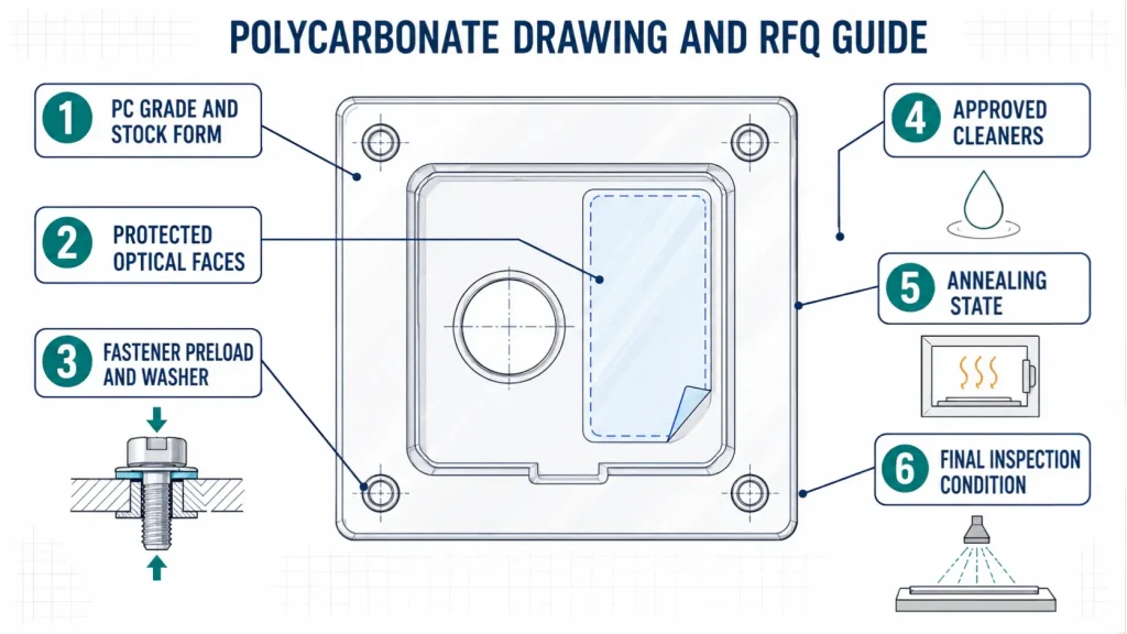
For a useful review, provide the STEP model and controlled 2D drawing together with the exact PC grade, stock form, protected faces, visible zones, critical dimensions, fastener condition, chemical exposure, annealing requirement, inspection state, and required evidence.
Rapid Efficient can review these factors with the proposed machining, finishing, inspection, and packaging route before quotation. For suitable custom polycarbonate components, submit the complete project information through our CNC machining services page.