Thread classes define the permitted dimensional variation and, where applicable, allowance of a screw thread. They help establish how mating threads fit and how each threaded feature should be inspected.
For Unified inch threads, A identifies an external thread and B identifies an internal thread. Metric designations such as 6g and 6H use a different system: the number identifies the tolerance grade, while the letter identifies the tolerance position.
For a CNC component, reading the class is only part of the decision. The mating thread, coating requirements, and inspection condition must also agree. A thread that passes inspection before plating may require different acceptance limits after finishing.
Read the Whole Thread Designation
A class cannot define a thread by itself. It belongs with the nominal diameter, pitch or threads per inch, and thread system.
| Example designation | Thread being specified | How to read it |
|---|---|---|
| 1/4-20 UNC-2A | External Unified inch thread | 1/4-inch nominal diameter, 20 threads per inch, UNC series, Class 2A |
| 1/4-20 UNC-2B | Internal Unified inch thread | The same nominal diameter and pitch, with an internal Class 2B requirement |
| M10 × 1.5-6g | External metric thread | 10 mm nominal diameter, 1.5 mm pitch, tolerance class 6g |
| M10 × 1.5-6H | Internal metric thread | The same nominal diameter and pitch, with an internal 6H requirement |
These examples explain the notation. They are not a table of manufacturing limits, and the inch and metric examples are not interchangeable.
For the same Unified thread size and series, Classes 1A/1B have wider tolerances than 2A/2B, while 3A/3B have tighter tolerances. Class 2 is a common general-purpose choice, but the required class should follow the joint’s function and the applicable specification.
Metric notation separates tolerance width from tolerance position. In 6H, the uppercase H identifies an internal tolerance position with zero fundamental deviation. In 6g, the lowercase g identifies an external tolerance position below the basic profile, providing allowance.
The numeral 6 does not mean that a metric thread is more precise than a Unified Class 3 thread. The systems use different definitions.
Some metric callouts contain two tolerance codes, such as 4g6g. The first applies to pitch diameter; the second applies to the external major diameter. For internal threads, the second code applies to minor diameter. A single code is used when the applicable grade and position are the same for both.
Use the limit tables from the specified thread standard and edition. For the other information needed on a threaded-hole drawing, including usable thread depth, see our tapped hole versus threaded hole guide.
Allowance and Tolerance Change Different Things
Allowance sets an intentional offset between mating thread limits. Tolerance defines how much a controlled dimension may vary.
Pitch diameter is central to this distinction. It is the diameter of an imaginary cylinder where, for an ideal thread, the thread ridge and adjacent groove have equal widths in an axial section. Measuring the outside diameter with a caliper does not establish pitch diameter.
For Unified external threads, Class 2A includes an allowance below the basic pitch diameter. Class 3A has no allowance and uses a tighter tolerance. Zero allowance does not mean zero manufacturing tolerance, and it does not turn a standard Class 3 thread into an interference fit.
The distinction matters when a drawing is changed from 2A to 3A. The change affects both the permitted variation and the space available between the external thread limit and the basic profile.
Fastenal’s screw thread design reference explains these allowance and tolerance relationships, including how plating can use the allowance on certain external threads.
For a mating pair, inspect the limits of both components. Specifying a tighter external thread while leaving the internal thread unchanged does not, by itself, define the finished assembly’s full range of clearance.
A Tighter Class Does Not Solve Every Joint Problem
Before changing the class, identify what is failing.
If parts have excessive movement during adjustment, the mating pitch-diameter limits may deserve review. If a fastened joint loosens after tightening, preload, contact surfaces, loading, and the locking method also need attention. A closer thread fit alone does not establish adequate clamp load.
Likewise, thread class does not specify material strength. A metric property class such as 10.9 describes fastener mechanical properties; 6g describes thread tolerances. They answer different questions.
A tapped aluminum housing also needs adequate thread engagement and material strength. Changing its internal thread from 2B to 3B does not automatically provide the engagement needed to resist stripping.
For a feature that must locate another component precisely, define the locating requirement separately. A shoulder or pilot diameter may establish the required position while the thread supplies retention. Do not assume the thread class alone controls the alignment of the complete assembly.
Tighter tolerances can reduce the manufacturing window. Tool wear, process variation, burrs, and finishing changes then become more significant relative to the permitted limits. Specify that tighter window when the assembly needs it, and confirm how it will be produced and inspected.
The choice between tapping and thread milling remains a separate process decision. Our thread milling versus tapping guide covers the tool-access and machining considerations behind that choice.
Budget the Coating at the Pitch Diameter
Plating builds up on thread flanks as well as on crests. For an ideal 60° thread with a uniform deposited thickness \(t\), measured normal to the flanks, the pitch-diameter change is approximately:\[ |\Delta PD| \approx 4t \]
The external pitch diameter increases. The internal pitch diameter decreases.
This is different from the familiar \(2t\) diameter change for coating a plain cylindrical surface. Vermont Gage’s pre-plate thread guidance explains the 60° relationship and why both minimum and maximum coating thickness matter when calculating manufacturing limits.
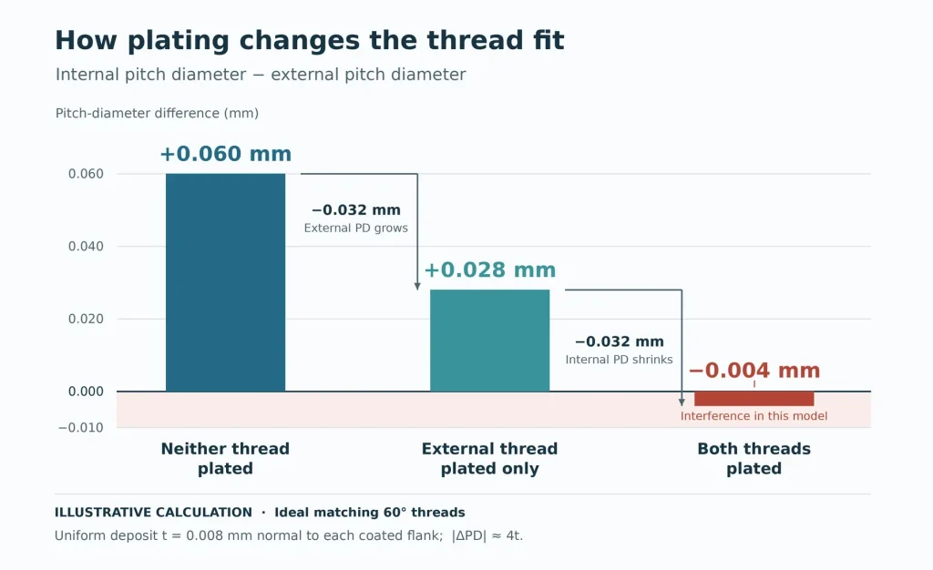
Consider an illustrative mating pair with an initial internal-minus-external pitch-diameter difference of 0.060 mm. Assume ideal matching thread geometry and a uniform deposit of 0.008 mm on each surface being plated.
These are calculation inputs, not standard limits for 2A/2B or 6H/6g.
| Coating condition | External pitch-diameter change | Internal pitch-diameter change | Remaining pitch-diameter difference |
|---|---|---|---|
| Neither thread plated | 0 | 0 | 0.060 mm |
| Only the external thread plated | +0.032 mm | 0 | 0.028 mm |
| Both threads plated | +0.032 mm | −0.032 mm | −0.004 mm |
For the last row:\[ 0.060 – (4 \times 0.008) – (4 \times 0.008) = -0.004\text{ mm} \]
The negative result indicates pitch-diameter interference in this simplified model. It is not a calculation of axial backlash, and it does not account for lead error, flank-angle error, or uneven deposits.
Coating both mating threads consumes the fit space from both sides.
For production, use the specified coating range and the applicable thread acceptance rules. Some specifications allow coating to consume an external thread’s allowance. Others require stated final limits to remain satisfied after finishing. Do not assume that the same gauge limits apply before and after coating.
Anodizing also needs separate treatment because part of the oxide forms within the original material. Total oxide thickness is not automatically equal to outward dimensional growth. The surface finishes guide provides broader context for coordinating finish requirements with machined features.
Match the Gauge to the Product and Its Acceptance State
Inspection starts with the product requirement: thread standard, nominal size, pitch, class, and condition at acceptance.
External threads are commonly checked with working thread ring gauges. Internal threads use working thread plug gauges. The gauges must match the specified acceptance limits, including any special requirements for coating.
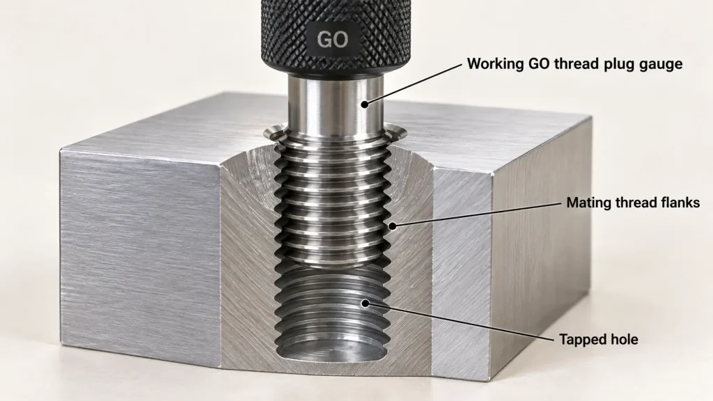
A setting plug is different. It is used to set or check an adjustable thread ring gauge. It should not be substituted for a working plug gauge when inspecting a tapped hole.
The cutting tool’s designation is another separate matter. An H3 tap limit describes the tap’s pitch-diameter range; it does not mean that the resulting hole is automatically a Class 3B thread. Select the tool to produce the required product limits, then inspect against those limits.
For a plated component, agree on the pre-plate process limits and the final acceptance limits before machining. A pre-plate inspection can control the allowance left for finishing. Final inspection must address the thread in the condition in which it will be delivered.
GO and NO-GO checks must follow the applicable gauging standard. Do not apply a universal NO-GO turn count to every thread system. Also confirm which requirements need separate checks, such as major or minor diameter, full thread depth, and location relative to the drawing datums.
A trial assembly with one available bolt is useful troubleshooting evidence. It does not replace the specified inspection method or establish interchangeability across the permitted range of mating parts.
For a threaded CNC component, share both mating thread callouts where available, the coating type and thickness range, the surfaces to be coated or masked, and the required inspection condition. Through our CNC machining services, RapidEfficient can review the machining requirements and coordinate the proposed finishing and thread-inspection plan before quotation.