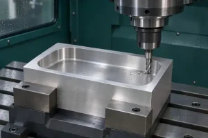

A small pocket can take longer to mill than its programmed feed suggests, even on a machine with a high-speed spindle. The axes still need time to slow down, turn, and accelerate again. Raising RPM does not remove those movements or establish the feed maintained around the part.
When comparing high speed machining proposals, connect the claimed saving to the actual feature: where the tool can sustain its feed, where cutting engagement changes, and how the finished contour will be preserved. Then compare elapsed time for the same completed operation.
The term can describe a cutting approach or a machine-control option. Ask which toolpath, tooling, and control functions the supplier proposes to use. A maximum spindle-speed specification alone does not answer that question.
Cutting speed also depends on cutter diameter. A small cutter can require high RPM without producing the same cutting speed as a larger cutter. Our aluminum milling cutting-speed guide explains that distinction and the related feed terms.
Short Moves May Never Reach the Programmed Feed
The axes need distance to accelerate. They also need to slow down before a stop or a direction change that cannot be taken at the current speed.
Look-ahead lets the control examine upcoming motion before executing it. Suitable paths can then be linked with fewer unnecessary slowdowns. Haas’s explanation of high-speed motion control describes how upcoming direction changes and acceleration limits affect the velocity through a program.
This does not mean every short line of code starts and ends at zero speed. A series of short, nearly aligned moves may run smoothly when the control can process and blend them. A tight turn can require a slowdown even when the program uses a single arc.
Consider a deliberately simplified straight move with these assumptions:
- The motion starts and ends at rest.
- The target speed is 6,000 mm/min, or 100 mm/s.
- Acceleration and deceleration are each constant at 1,000 mm/s².
- Jerk limits, axis coupling, and cutting forces are excluded.
Reaching 100 mm/s takes 5 mm of acceleration distance. Stopping from that speed takes another 5 mm. The move therefore needs 10 mm just to accelerate and decelerate, with no distance left for steady travel.
| Move length | Highest speed reached in this model | Total motion time |
|---|---|---|
| 2 mm | Approximately 2,680 mm/min | Approximately 0.089 s |
| 30 mm | 6,000 mm/min | 0.400 s |
The 2 mm move must begin slowing before it reaches the target speed. Dividing its length by the programmed feed would give only 0.020 s, which excludes the required acceleration and deceleration.
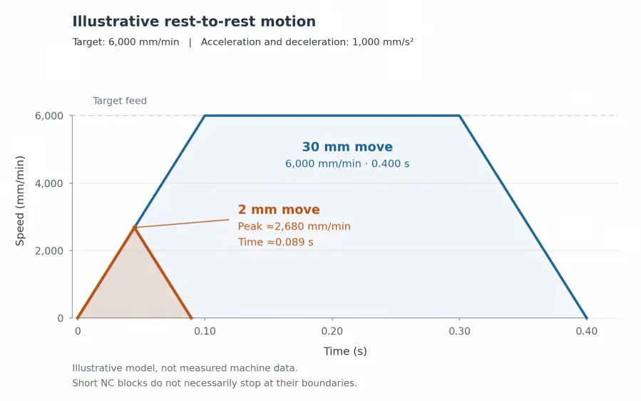
These are illustrative motion calculations, not machine specifications or predicted cutting times. Real controls may carry speed across adjacent blocks. Use the example to question a time estimate, not to impose a minimum CAM segment length.
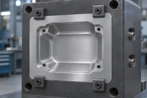
A Pocket Corner Can Limit Motion and Cutting at Once
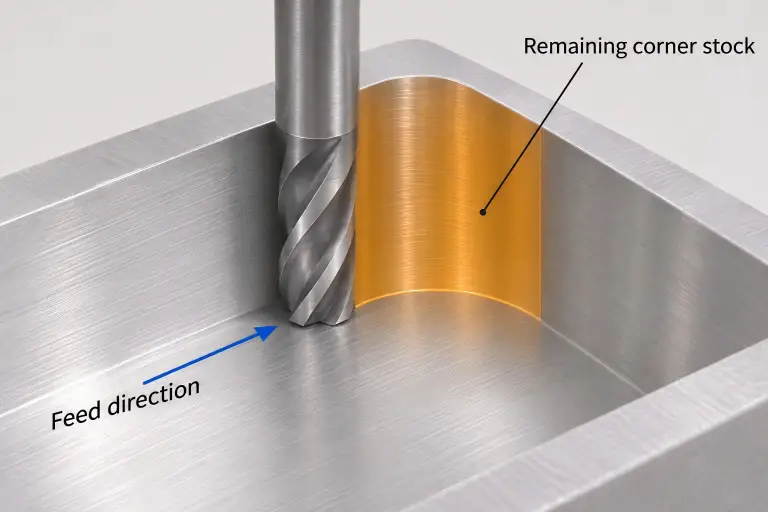
At an internal corner, two different constraints can appear together.
First, the tool-center path changes direction. The machine must make that turn within its motion limits and permitted path deviation.
Second, the cutter may contact more material around its circumference. This increased arc of engagement can raise cutting load even if the programmed feed is unchanged. Sandvik Coromant’s guidance on milling inside corners explains the engagement change and its connection to vibration and edge damage.
A smooth tool-center path does not, by itself, establish smooth cutting load. The remaining stock matters as well.
| Location in the pocket | Motion question | Cutting question |
|---|---|---|
| Long straight wall | Is there enough travel to sustain the intended feed? | Are radial engagement, tool reach, and chip removal suitable? |
| Internal corner | How tightly must the tool-center path turn? | Does the remaining stock increase the arc of engagement? |
| Corner cleanup after roughing | Does a smaller tool follow many short transitions? | How much stock did the larger roughing tool leave locally? |
A controlled-engagement roughing path may take a longer route while avoiding sudden load increases. That can be useful, but a longer path with a higher programmed feed is not automatically faster. Compare the executed operation, including entries, linking moves, and any later corner cleanup.
Changing the roughing path also does not authorize changing the finished corner radius. If a larger finished radius would help, it requires design approval when it falls outside the drawing limits.
Smoothing Must Fit Within the Finished Contour
Control settings can allow smoother transitions by permitting a bounded deviation from the programmed path. That allowance has to fit the machining stage and the part requirement.
HEIDENHAIN’s explanation of Cycle 32 TOLERANCE shows how permitted contour deviation affects attainable feed. It also distinguishes roughing settings from the tighter settings needed for finishing. The named cycle belongs to that control system; it is not a universal setting for every machine.
For a pocket with finish stock remaining, roughing may tolerate a different path allowance from the final wall pass. Check that the roughing motion leaves enough material everywhere for finishing. A faster roughing pass that removes required wall material cannot be repaired by the finishing pass.
CAM path tolerance, control smoothing, and drawing tolerance describe different things. They must be considered together with tool deflection and other process errors. Giving the control the entire drawing tolerance leaves no deliberate allowance for those other errors.
Compare speed proposals using the same final wall profile, corner radius, and surface requirement. A faster result obtained by accepting a different contour is a different proposal.
Compare the Same Finished Pocket and the Same Clock
Before accepting a cycle-time claim, establish what was timed. A CAM estimate, a dry run, and a measured cutting cycle provide different evidence. A CAM estimate may account for some machine behavior, depending on its configuration; it still needs checking against the proposed machine and program.
For two pocketing proposals, keep the comparison specific:
- Start from the same stock condition. A near-net blank and a solid block do not require the same removal work.
- Finish to the same requirement. Include corner cleanup and the passes needed to achieve the specified geometry and surface.
- Use the same timing boundary. State whether the measurement includes approaches, retracts, tool changes, probing, and handling. Keep one-time programming and setup costs visible separately.
- Identify the cutting conditions behind the result. Record the tool and holder, material condition, tool reach, and whether the result comes from a trial cut or an estimate.
- Connect time to acceptable parts. Check the corners and finished walls produced by the timed route. For repeat production, account for planned tool replacement and quality through the intended tool-use interval.
An impressive roughing time may save little if corner cleanup remains the longest operation. Likewise, a faster repeat cycle does not establish the delivery date when programming, setup, inspection, or outside finishing controls the order schedule. Our CNC turning and milling efficiency guide covers those wider production factors.
For a useful review, identify the pockets or contours behind the speed claim, mark the corner radii and surfaces that cannot change, and state whether the target is shorter machine time, a lower repeat-part cost, or an earlier delivery date. Include any existing timing record with its start and finish points.
Through our CNC machining services, RapidEfficient can review those requirements and coordinate a suitable machining proposal before quotation. The proposal should explain which part of the operation can improve and how the finished requirement will still be met.