
A long, thin section of a workpiece can deflect under cutting force. Swiss-type turning addresses that problem by supporting the bar in a guide bushing close to the cut. A conventional CNC lathe can also machine slender parts, using a suitable combination of workholding, tailstock support, and steady rests. The useful comparison is where each setup supports the work while each feature is being made.
Modern Swiss-type lathes are themselves CNC machines. Here, “Swiss lathe vs CNC lathe” means a sliding-headstock Swiss configuration compared with a conventional fixed-headstock CNC turning route. For a purchased part, the choice depends on its support needs, the available bar stock, and the sequence required to finish both ends.
Support at the Cutting Point
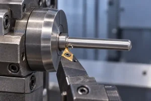
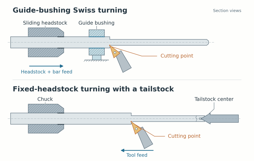
On a conventional fixed-headstock lathe, the work rotates in a chuck or collet while the tool travels along it. A portion projecting from the workholding can deflect under cutting force. A tailstock center supports the free end; a steady rest supports a suitable cylindrical surface along the workpiece. Their positions and the surfaces they contact affect which features remain accessible.
In a guide-bushing Swiss setup, the sliding headstock feeds rotating bar through a guide bushing near the tools. Material can be turned as it emerges, keeping the active cut close to the guide. Citizen’s explanation of fixed- and sliding-headstock lathes illustrates this support difference.
This distinction changes what “long” means in a quotation. A long finished pin may have been produced progressively with little material exposed between the guide and the active turning tool. Conversely, a shorter piece with a very thin neck may still be difficult if the operation leaves that neck poorly supported. Overall length-to-diameter ratio helps flag a question; the actual cutting and support positions answer it.
The advantage also has limits. A guide bushing fitted to the incoming bar diameter cannot provide the same close support to a section already turned substantially smaller. If a later operation requires pulling that reduced section back into the guide, the process planner must account for the changed support. The order of operations therefore matters as much as the machine label.
Broader drawing issues, including shoulders, bores, runout, and support surfaces, are covered in the CNC turning parts guide. The comparison below follows one geometry through two possible routes.
One Stepped Pin, Two Machining Sequences
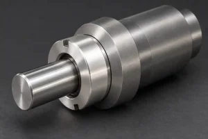
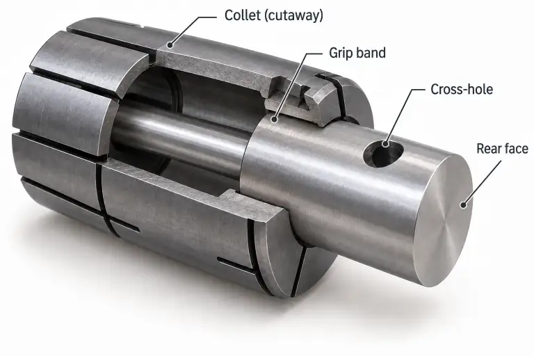
Consider an illustrative pin with a short front pilot, a long slender stem, and a larger rear collar. A cross-hole passes through the collar, and the rear face must be finished. Its material, dimensions, tolerances, and permitted contact marks would determine whether either proposed route is acceptable.
Guide-bushing Swiss route
- Start at the leading end. Feed the bar to the working position, face the end, and form the front pilot. Keep the active turning operation near the guide while the unmachined bar supplies support behind it.
- Produce the stem as the bar advances. Plan the turning passes so the slender region is finished progressively near the guide. Where the stem requires several machining segments, their transitions still have to meet the specified diameter and surface requirements. An unfinished detail that needs a later return to an unsupported region must be resolved in the sequence.
- Form and cross-drill the collar. Leave the larger rear feature until the preceding length has emerged. With suitable live tooling and access, the collar can be cross-drilled while the part remains attached to the bar. Hole breakout and burr removal belong in the process, including the interior of the cross-hole.
- Separate the part and finish the rear face. An equipped subspindle may grip an approved cylindrical land before cutoff, then present the rear face to backworking tools. The grip must suit the slender geometry and the allowed surface condition. If the configuration cannot perform this transfer and finishing operation, the route needs a separate holding and finishing step.
The key benefit in this example is support during progressive stem turning. Cross-drilling and backworking add value only when the actual machine configuration can perform them; conventional turning centers may have these capabilities too.
Fixed-headstock route with end support
- Prepare a blank and establish support. This example assumes the drawing permits a center hole in the front end. Use a cut blank with rear gripping allowance, hold that allowance in a chuck or collet, and support the front end with a tailstock center. If the finished part must have no center hole, the route needs either different support or front-end allowance and a later holding and finishing operation to remove it.
- Turn the pilot, stem, and collar. The tool moves along the supported blank. Tailstock support helps resist movement at the free end, but the slender span can still deflect. The supplier must choose a suitable cutting sequence and, where needed, additional support. Any steady-rest contact surface and its clearance from the tool must be identified.
- Make the cross-hole. Suitable live tooling can do this in the turning setup if the support hardware leaves access. Otherwise, a secondary drilling setup must locate the hole from the required part features and include deburring.
- Finish the gripping end. Rehold the part on a suitable surface to remove the rear allowance and finish the face. This operation must preserve the required relationship between the rear face and the turned features. A machine with suitable transfer capability may combine operations differently.
Both routes can lead to the same finished pin. They place different demands on the drawing: the Swiss proposal needs workable bar guidance and a sequence that preserves support; this fixed-headstock proposal needs an acceptable center location, gripping allowance, and second holding arrangement.
What Can Change the Route Choice?
The guide-bushing route depends on the incoming bar as well as the finished part. Have the supplier state the diameter variation, roundness, straightness, and surface condition accepted by the proposed feeding and guide-bush arrangement. These are purchasing requirements for that setup, rather than a universal bar specification.
Ground bar may be appropriate, but the requirement depends on the equipment. For example, Citizen’s adaptive guide-bush documentation describes a system that compensates for bar-diameter variation and permits suitable non-ground stock. That specific capability should be confirmed for the quoted setup before removing a grinding requirement from the material price.
A drawing revision can shift the balance. A collar much larger than the stem requires larger starting bar and more removal from the slender region in a round-bar Swiss route. A feature that must be revisited after the stem has passed the guide may require a different machining order or extra support. A prohibited center hole changes the fixed-headstock example above. These details can outweigh a simple preference for one machine type.
Short, rigid parts gain less from close guide-bushing support. Some Swiss machines offer a guide-bushless mode, with different working limits. Where that mode is proposed, evaluate its actual workholding and travel rather than carrying over the support assumptions of the guided route.
Quantity affects how the preparation is spread across the order. A repeat run may justify dedicated collets, guide-bush preparation, and coordinated front and back machining. For a small batch, an existing fixed-headstock setup with suitable support may require less preparation. The comparison still needs the same finished scope: a price that includes cross-hole deburring and rear-face finishing covers more work than one that stops at cutoff.
When discussing the pin through RapidEfficient’s CNC turning services, ask for the proposed support and holding positions to be marked on the part. State whether center holes and contact marks are allowed, and which surfaces control the rear face and cross-hole. Those annotations make the two machining proposals comparable before either route is selected.
For this pin, Swiss turning becomes attractive when progressive cutting keeps the thin stem supported and the remaining features fit the same sequence. A conventional route remains credible when its supports and later holding operations can complete the drawing reliably.